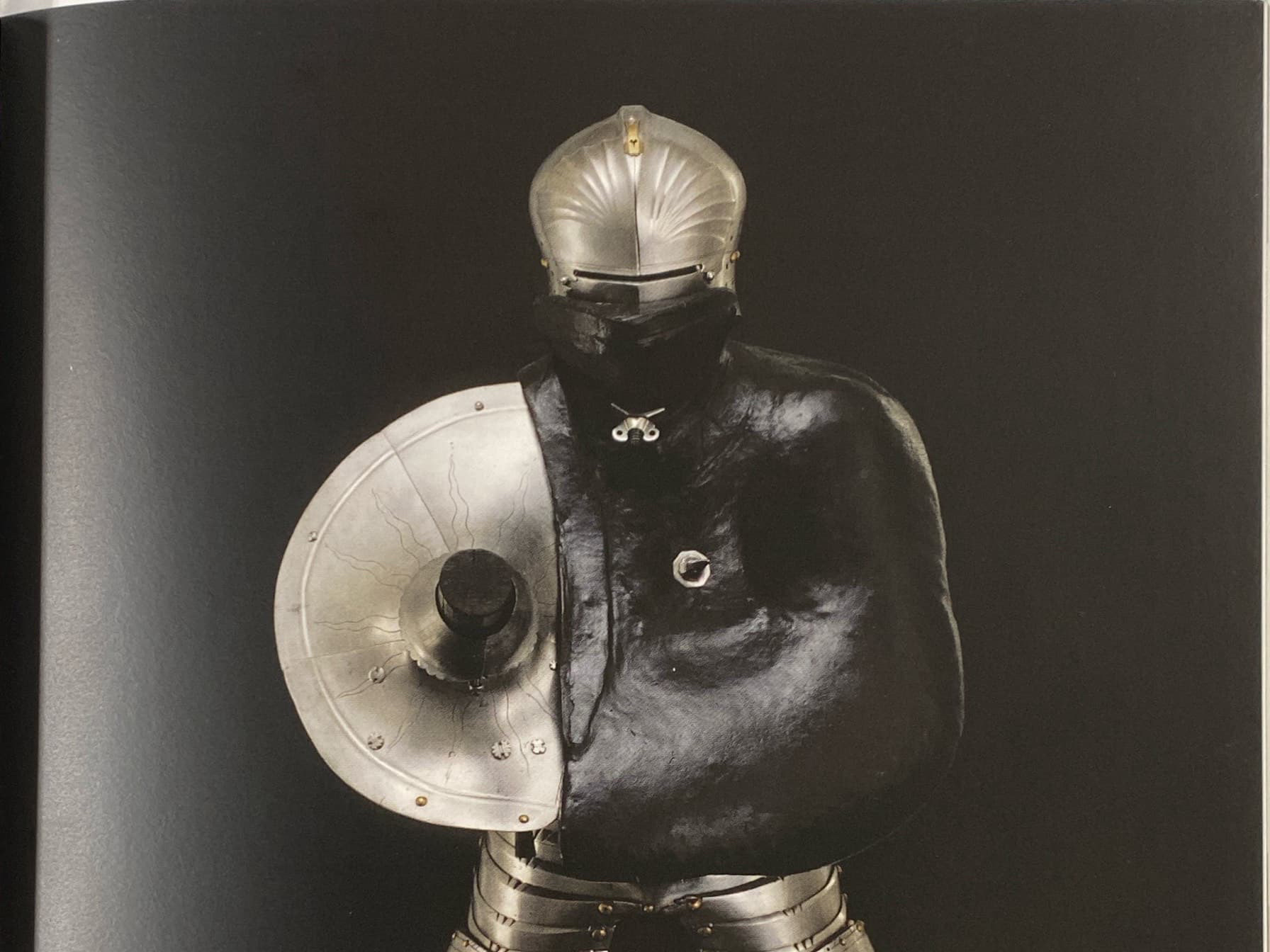
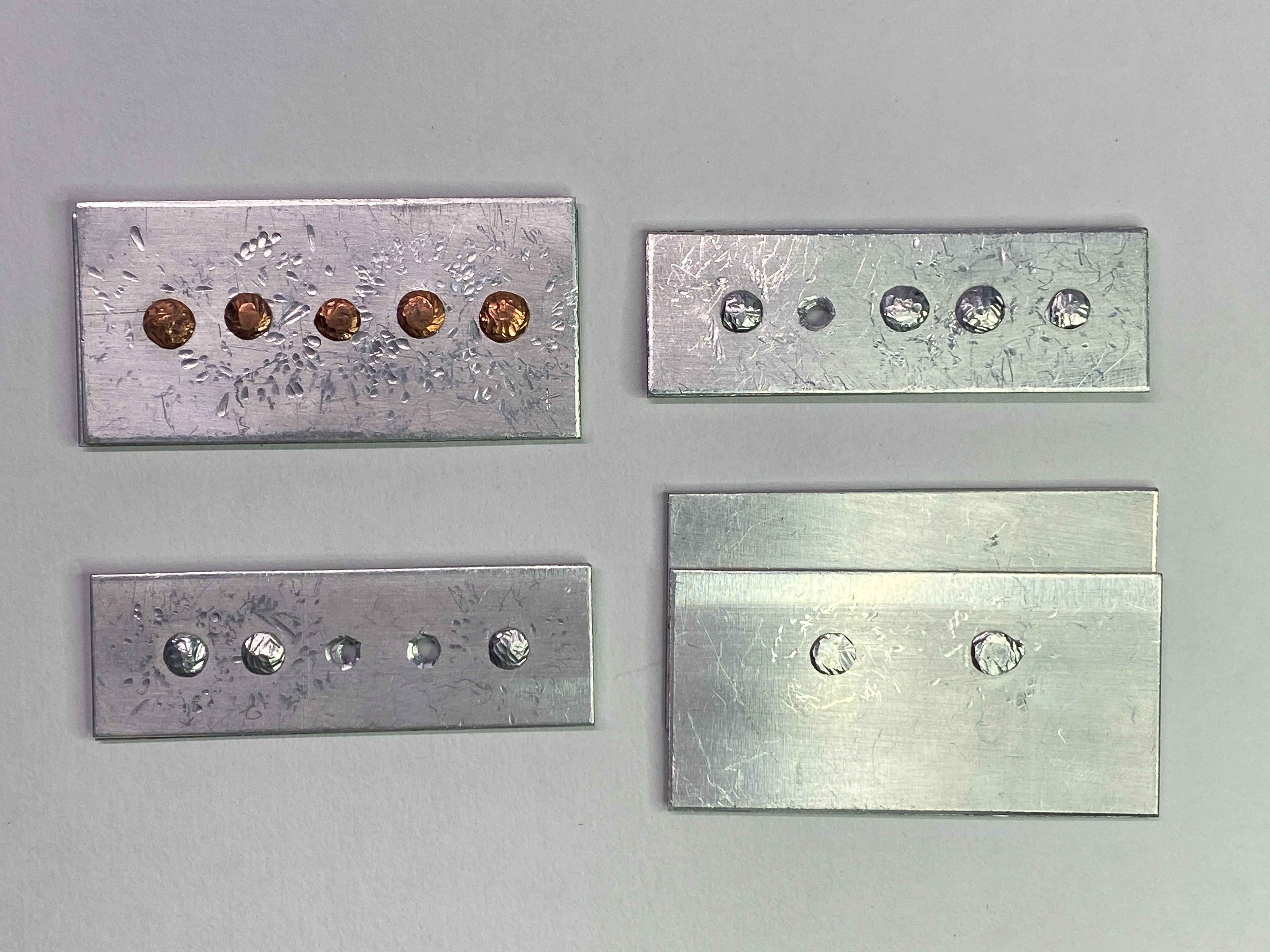
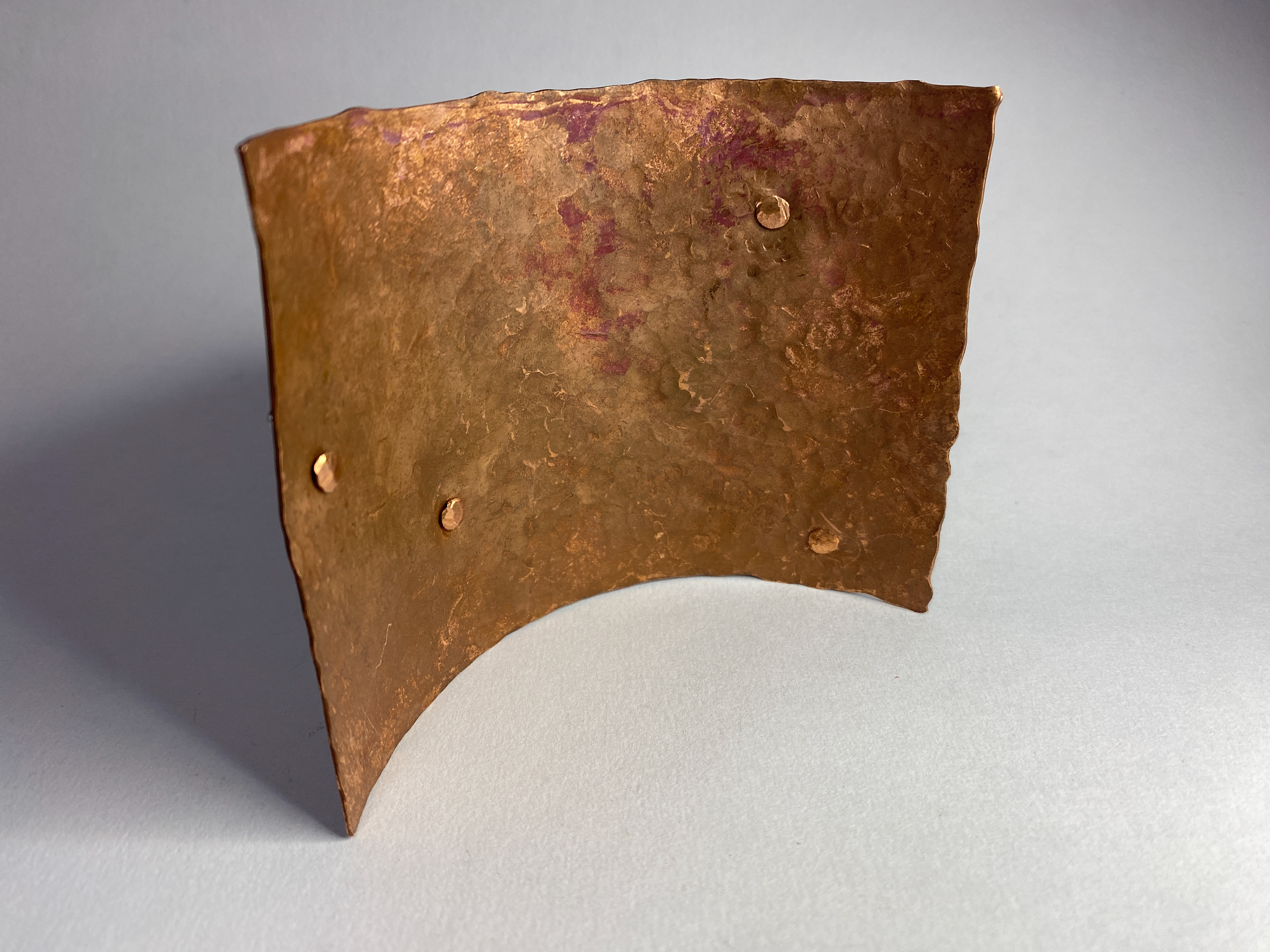
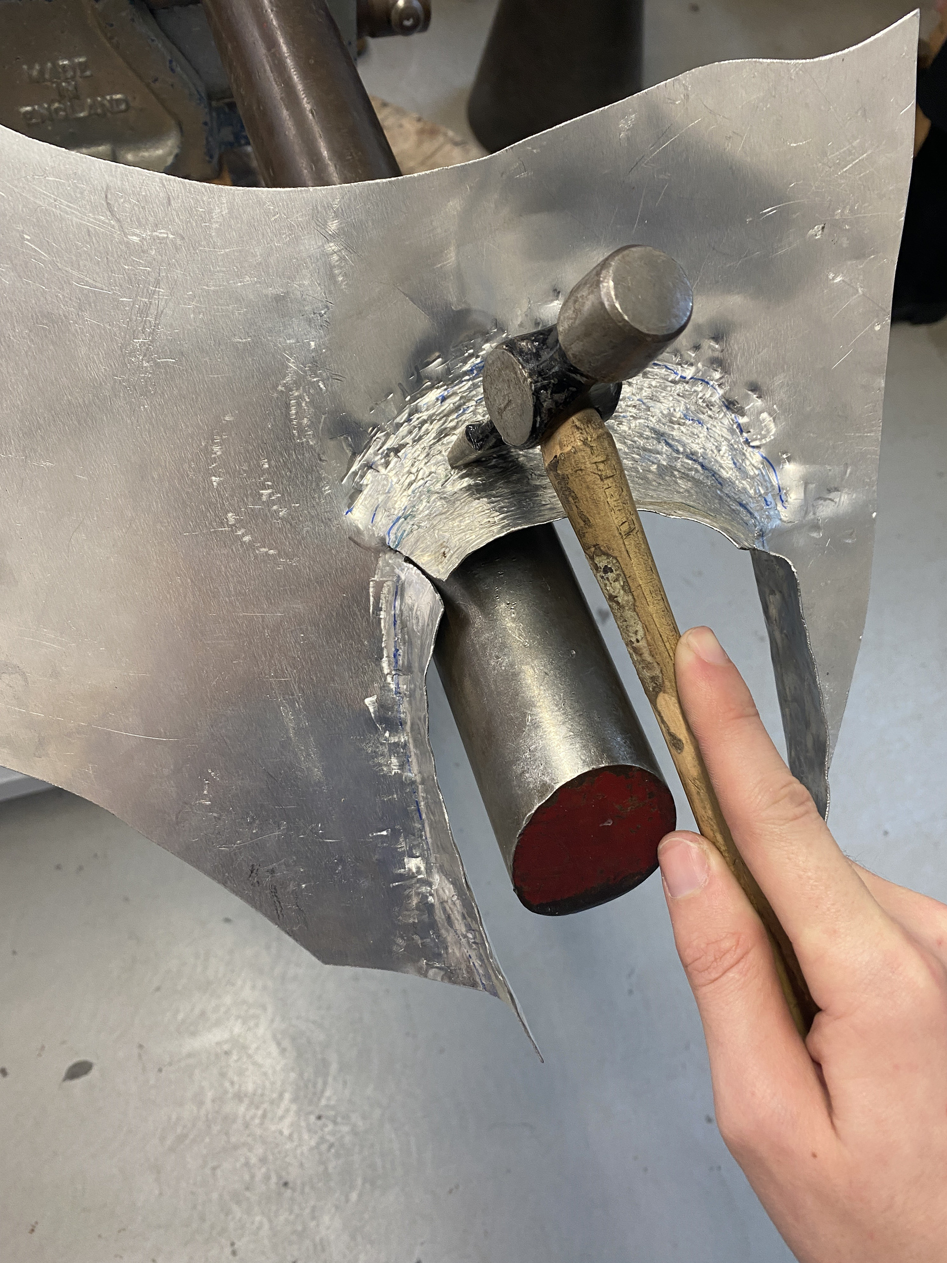
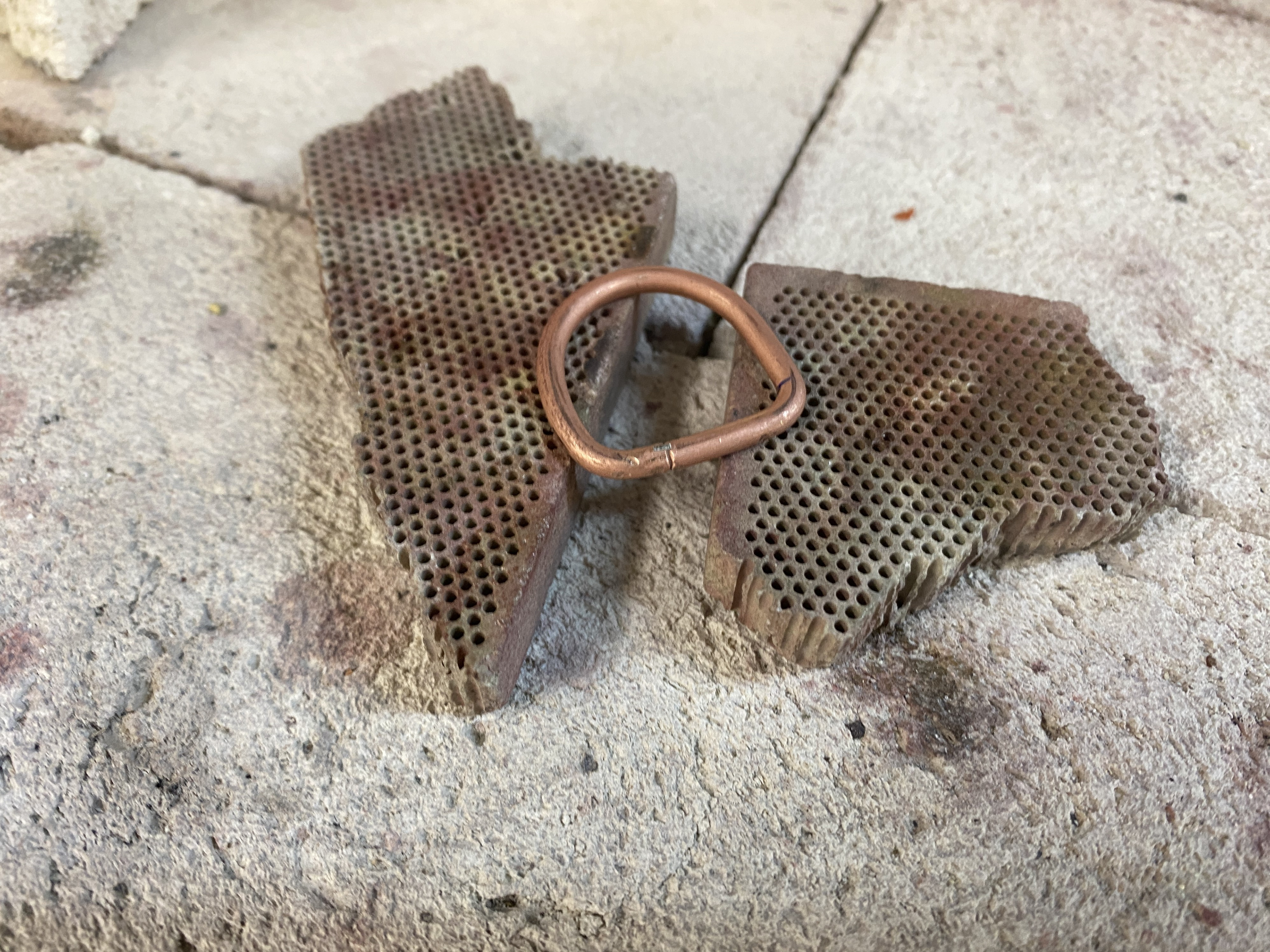
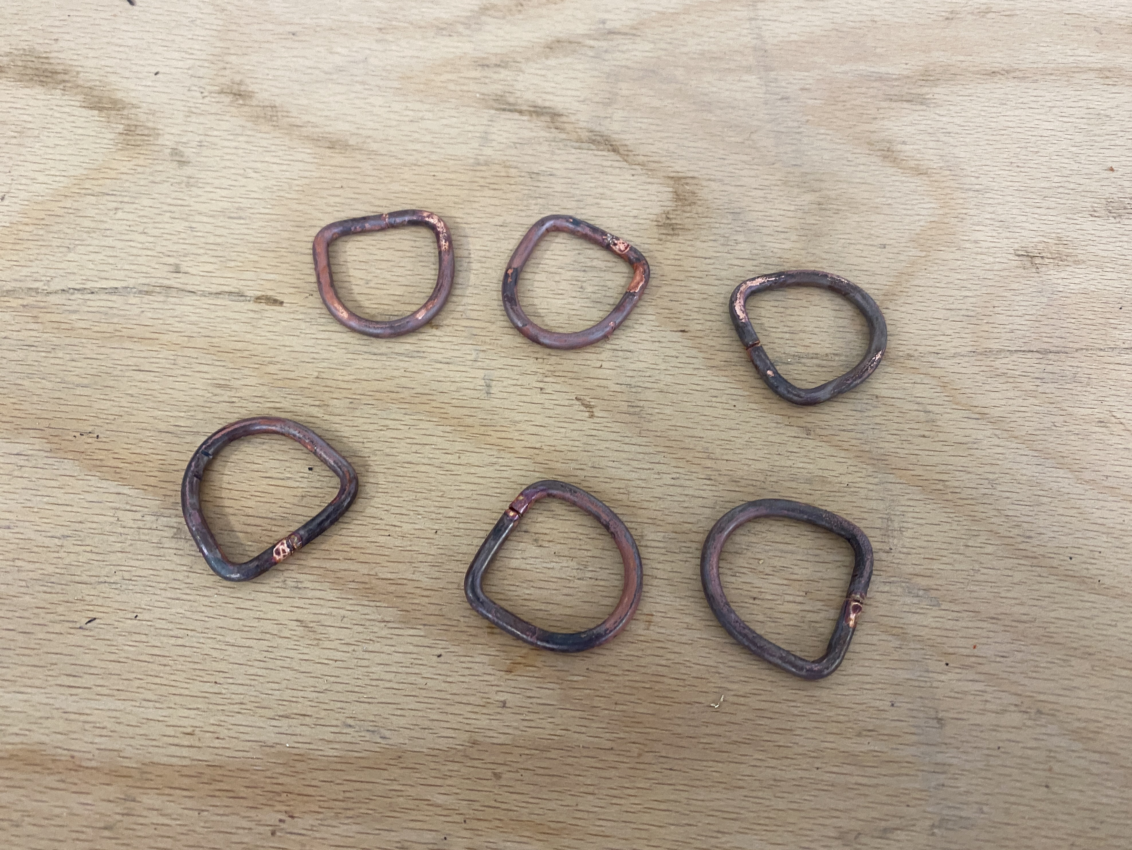
Reviewing last term's samples and inspiration from the Royal Armouries Museum Leeds, I needed to improve and practice my riveting to create secure and aesthetic connections. Therefore, I repeated the process many times analysing the order and positioning of the hammer blows to create a uniform domed face. I learned the importance of annealing the copper to make it easier to move into place, as well as increasing the size of the rivets using 3mm wire.
Another observation was the lettering laid over plain sheet metal looked too minimalist and unrefined. To make this more refined I would have to polish and ensure all elements were perfect to create a uniform aesthetic. However, through my primary research I liked the imperfections in the armour and the marks left in the surface that tell the history of the object. Therefore, I want to explore texturing the sheet metal by hand creating variety in texture and form.
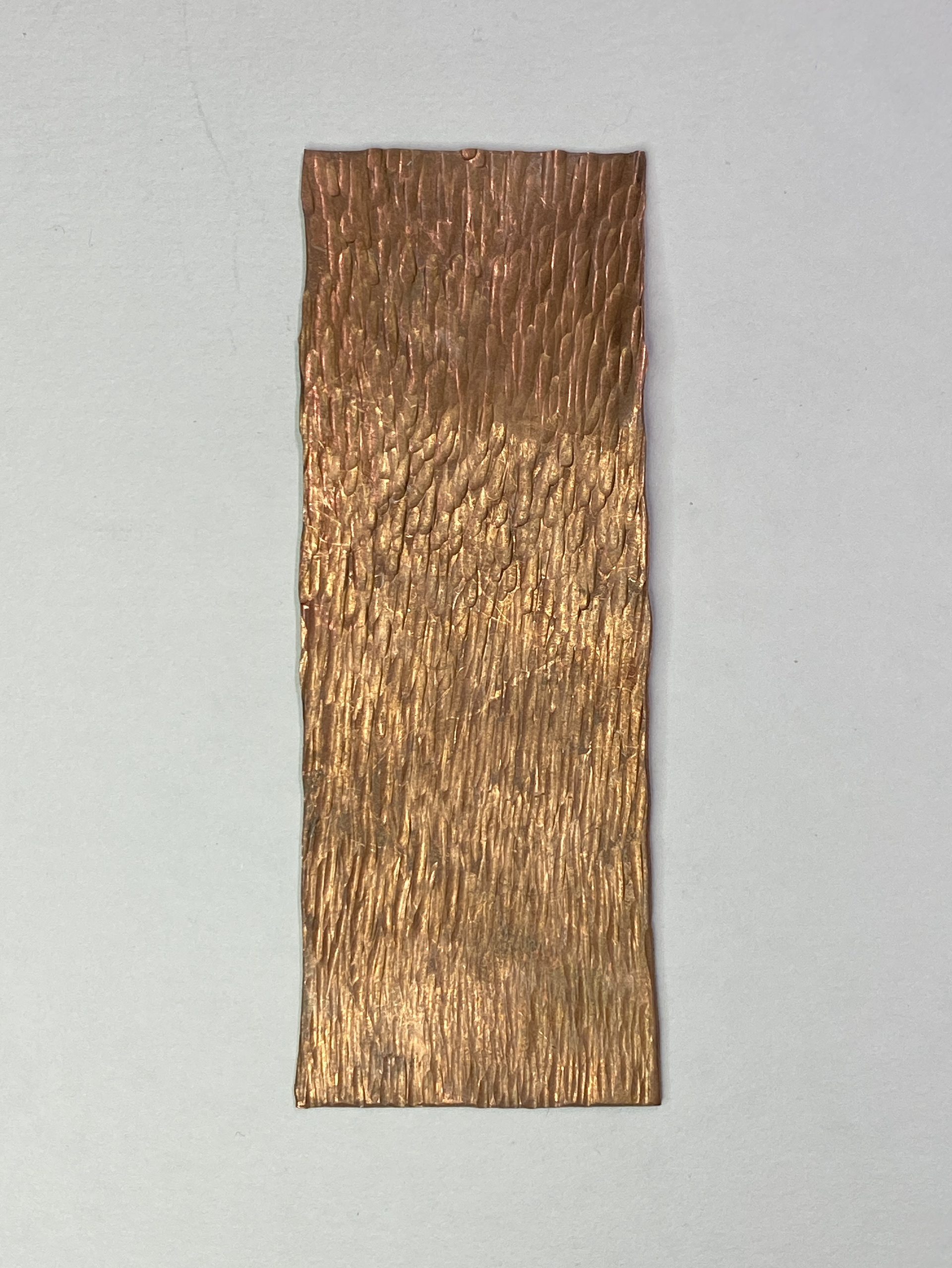
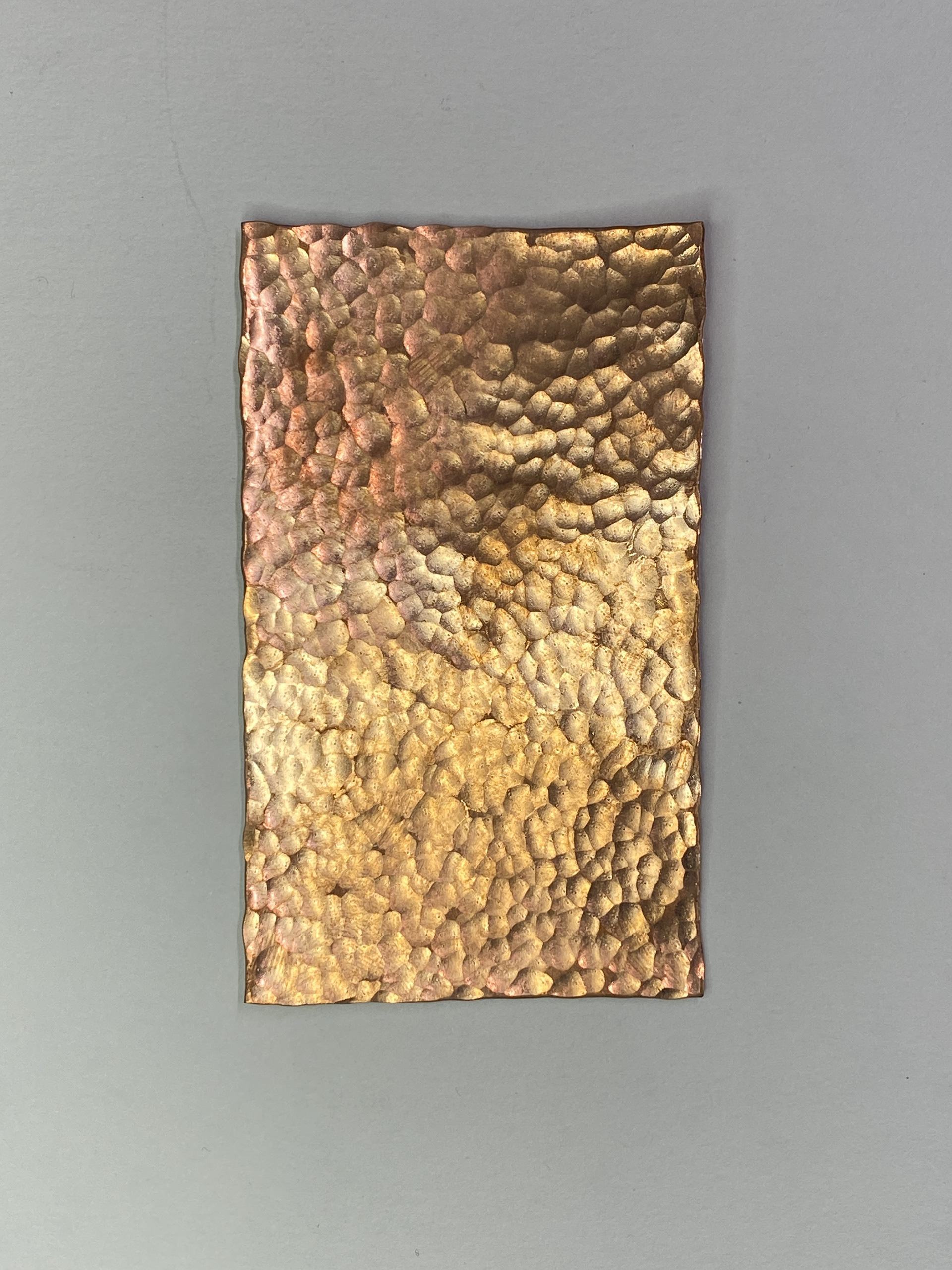
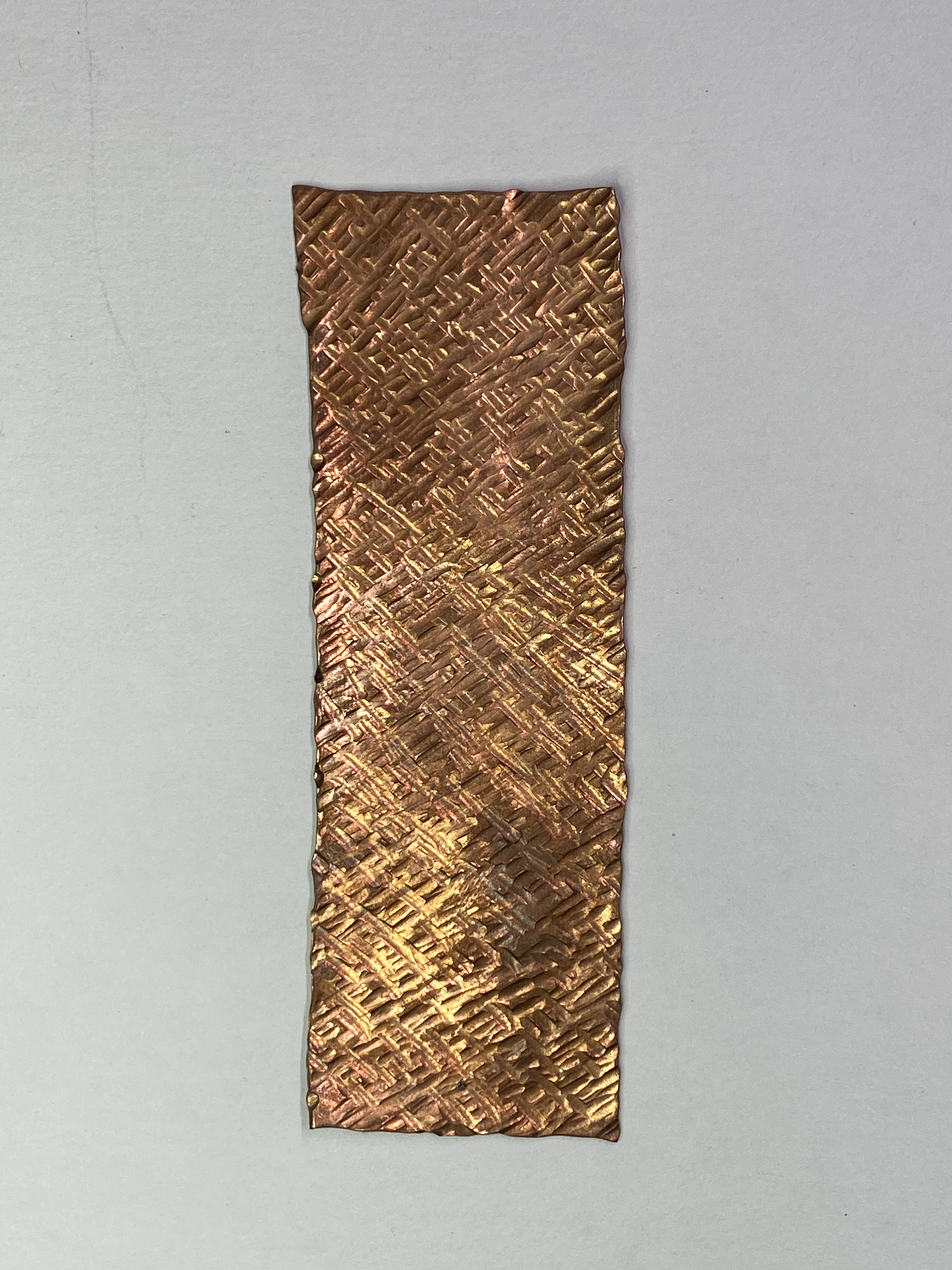
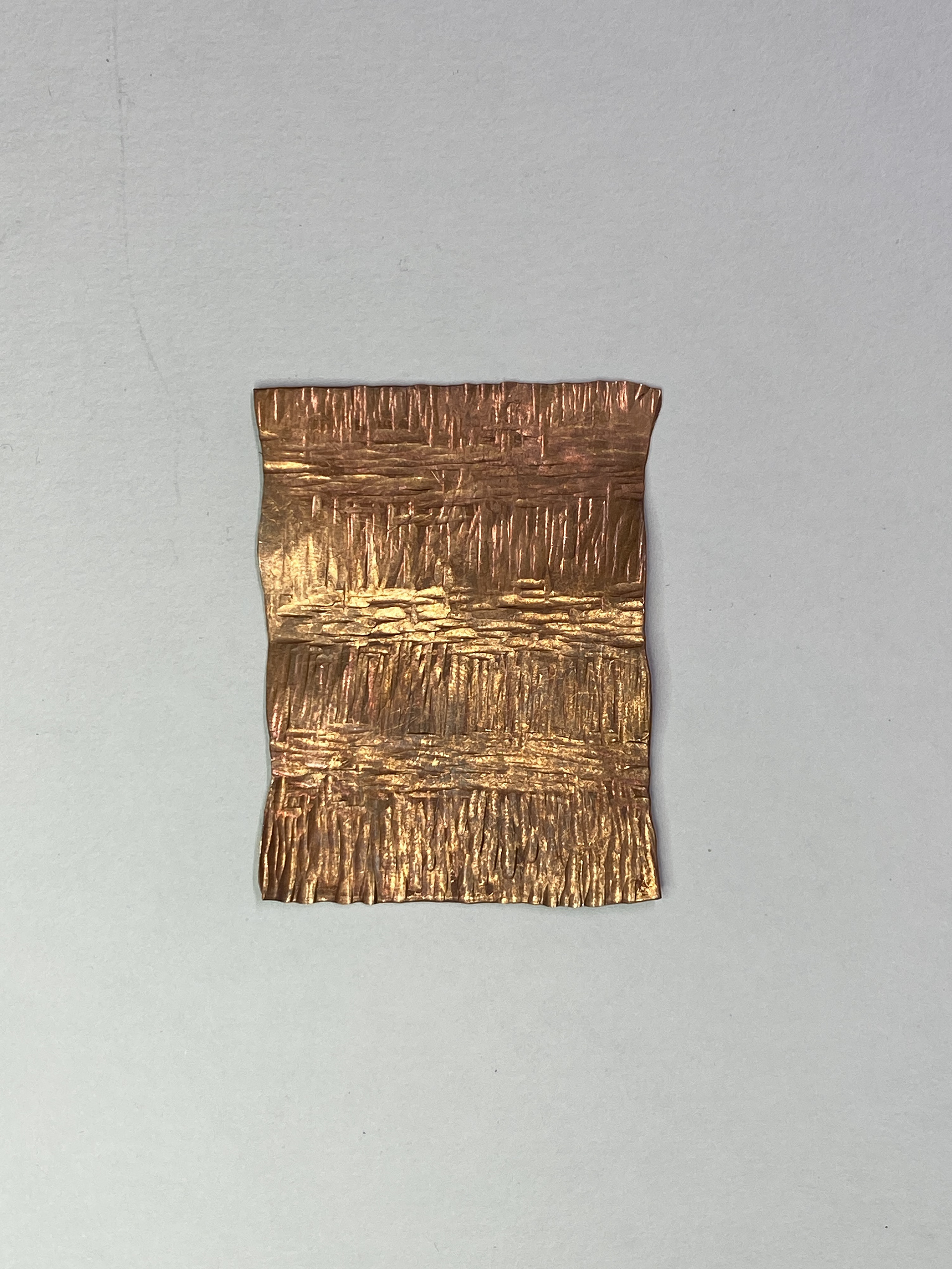
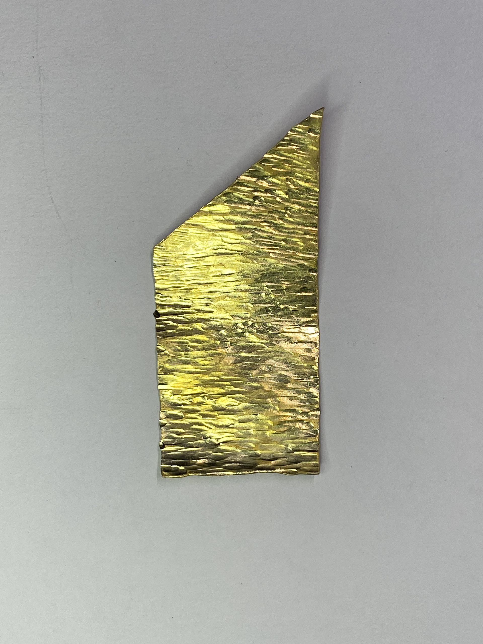
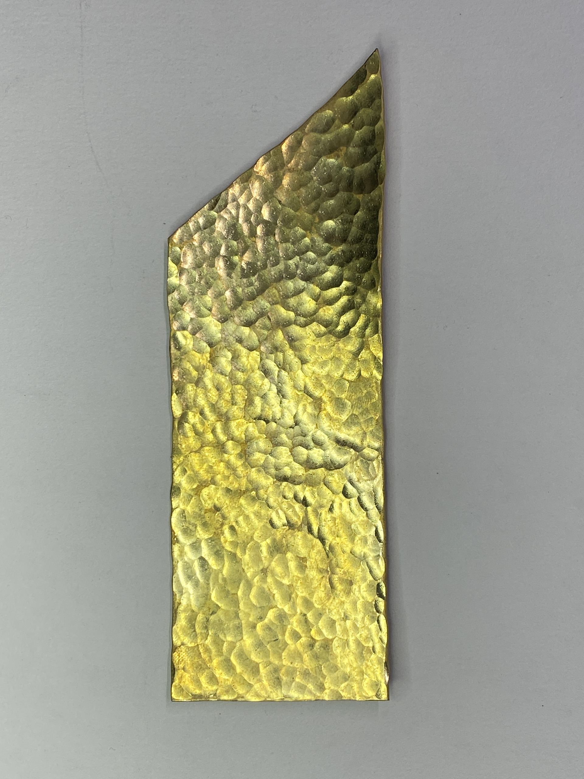
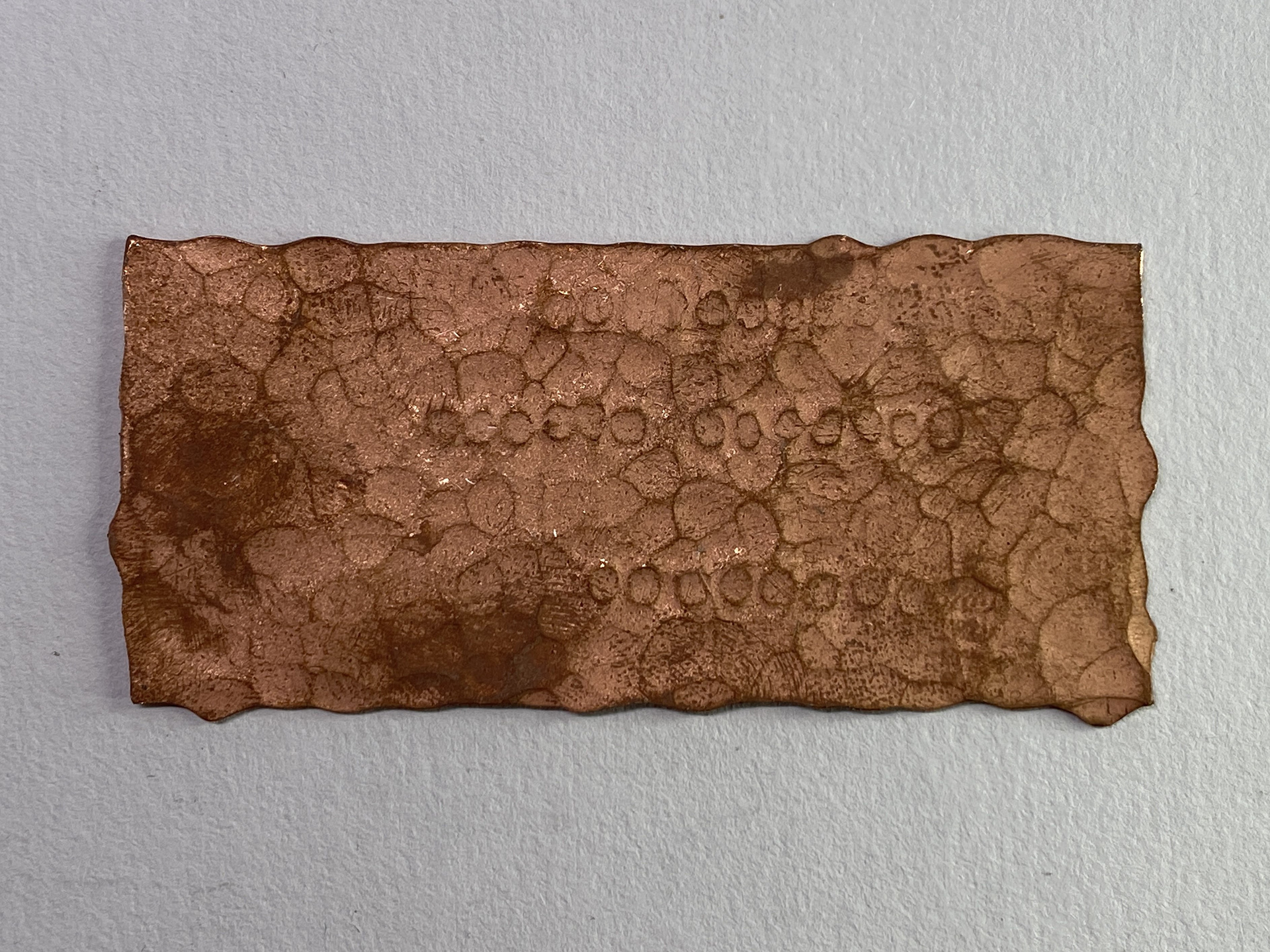
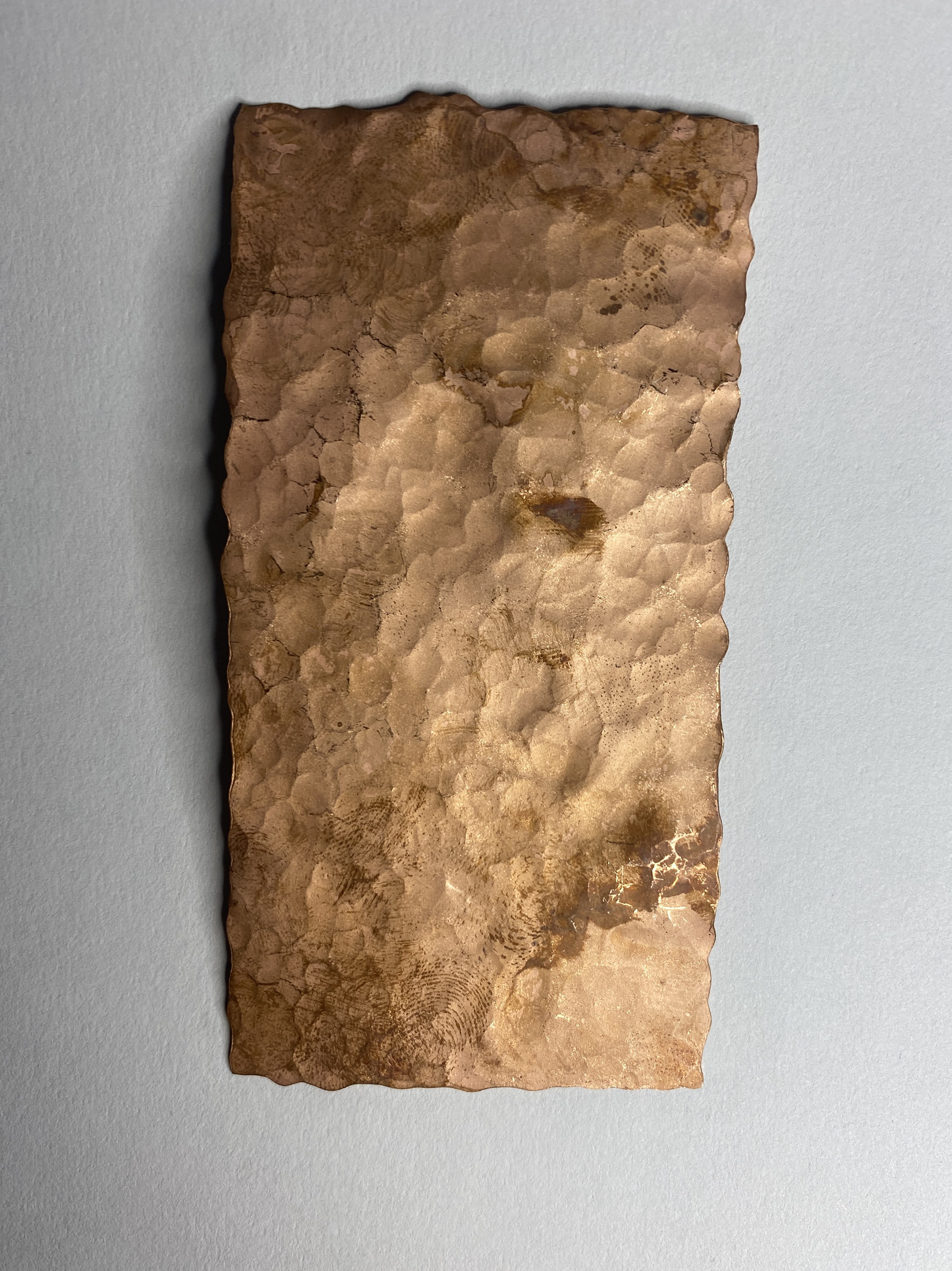
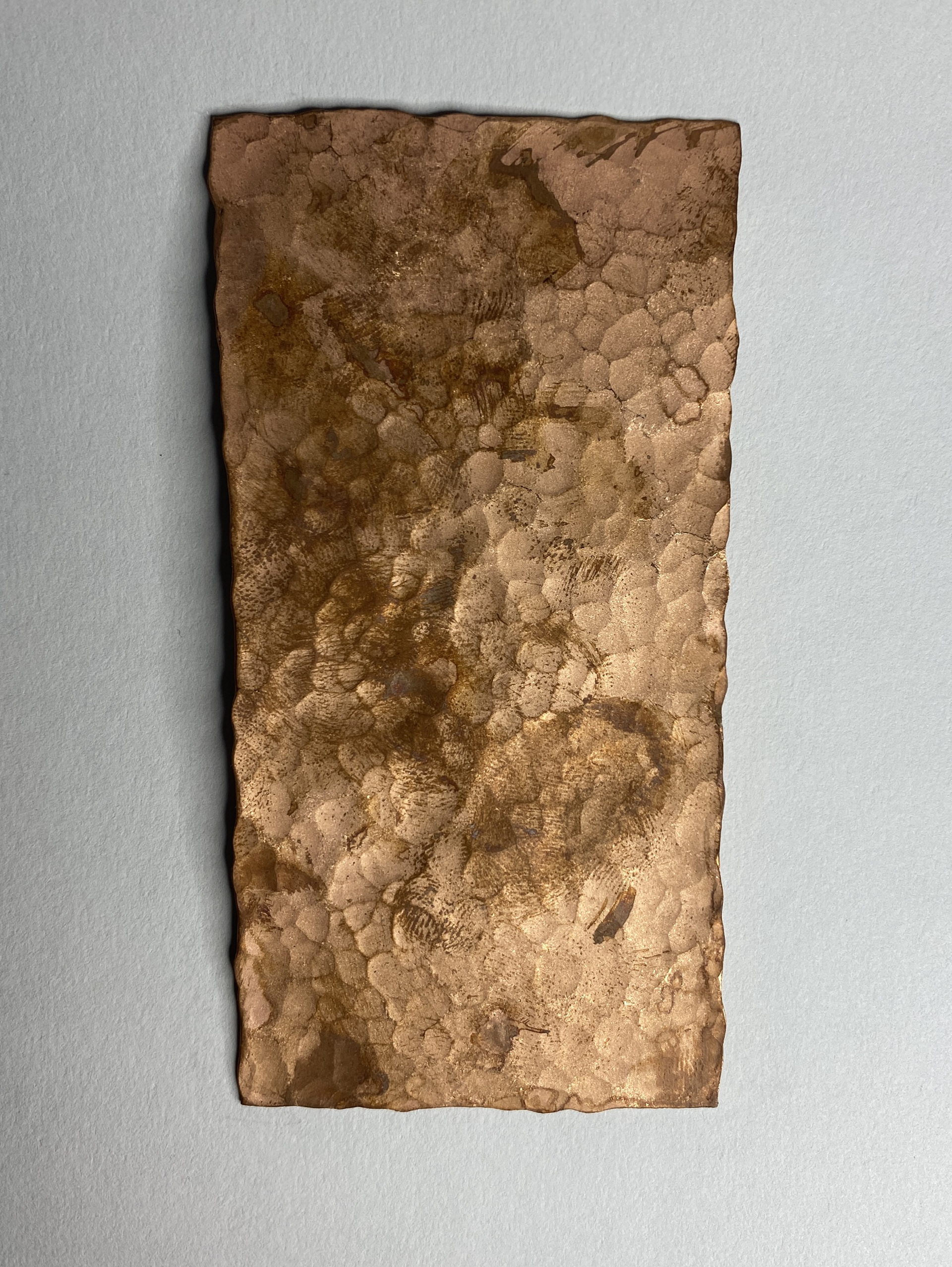
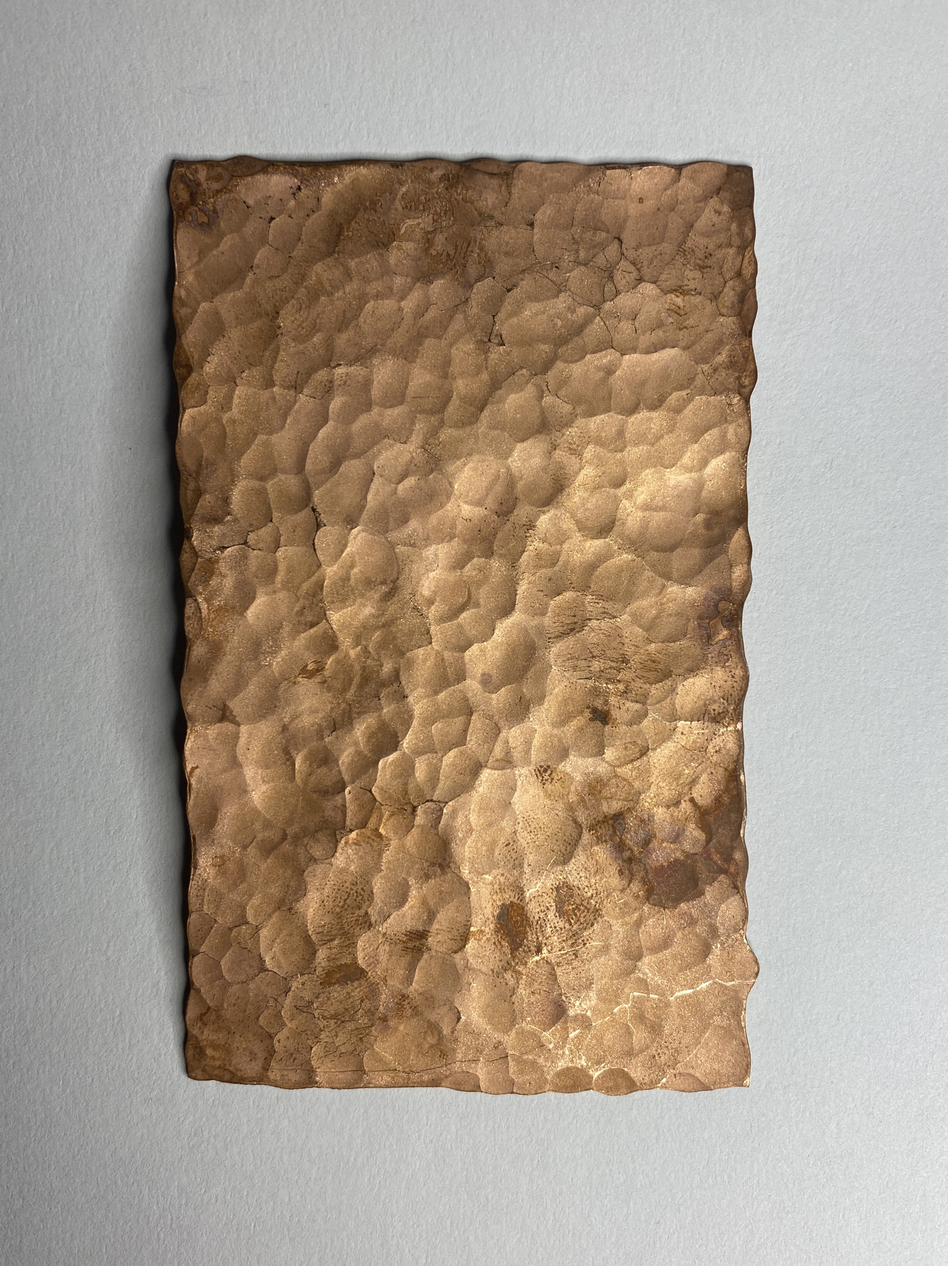
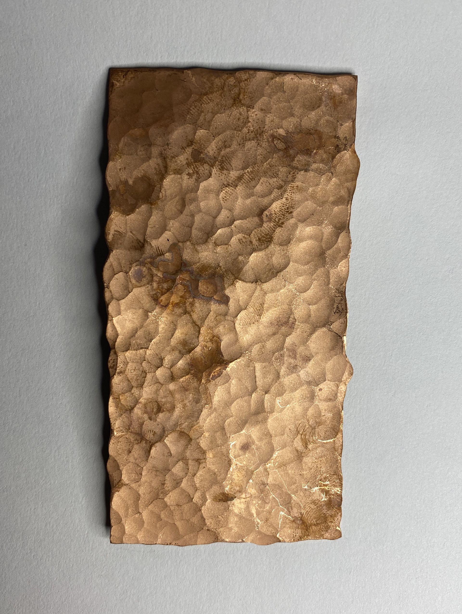
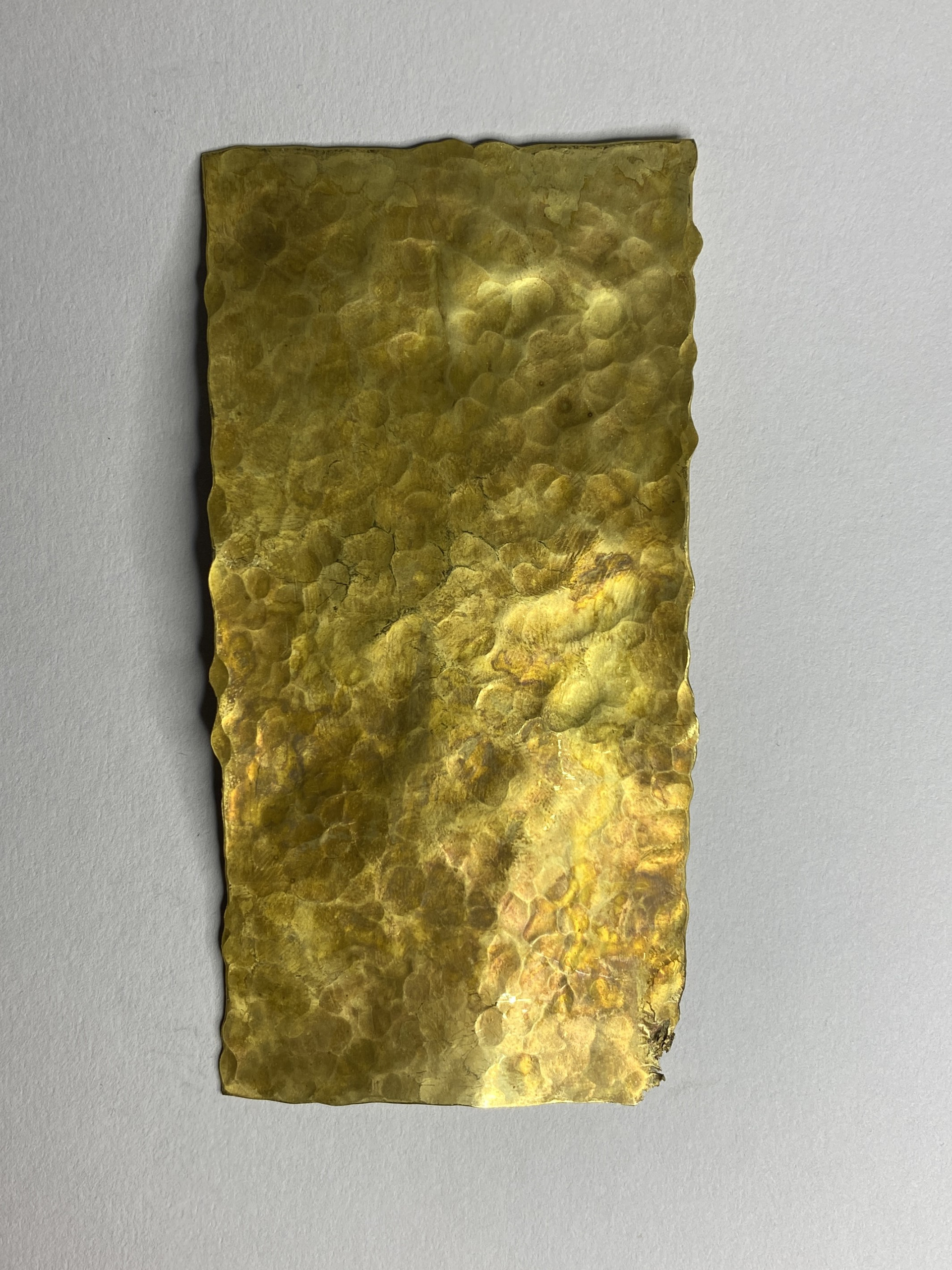
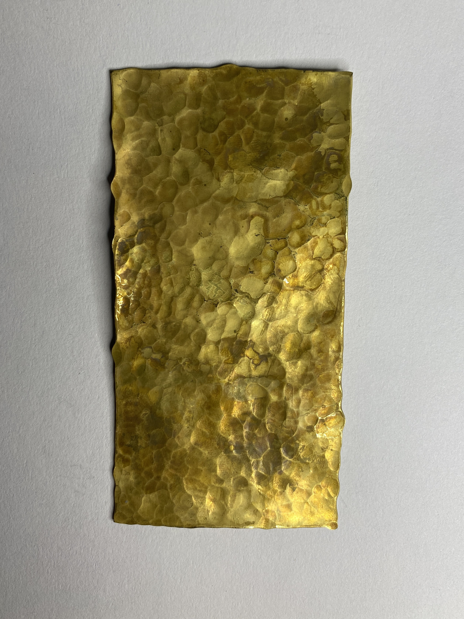
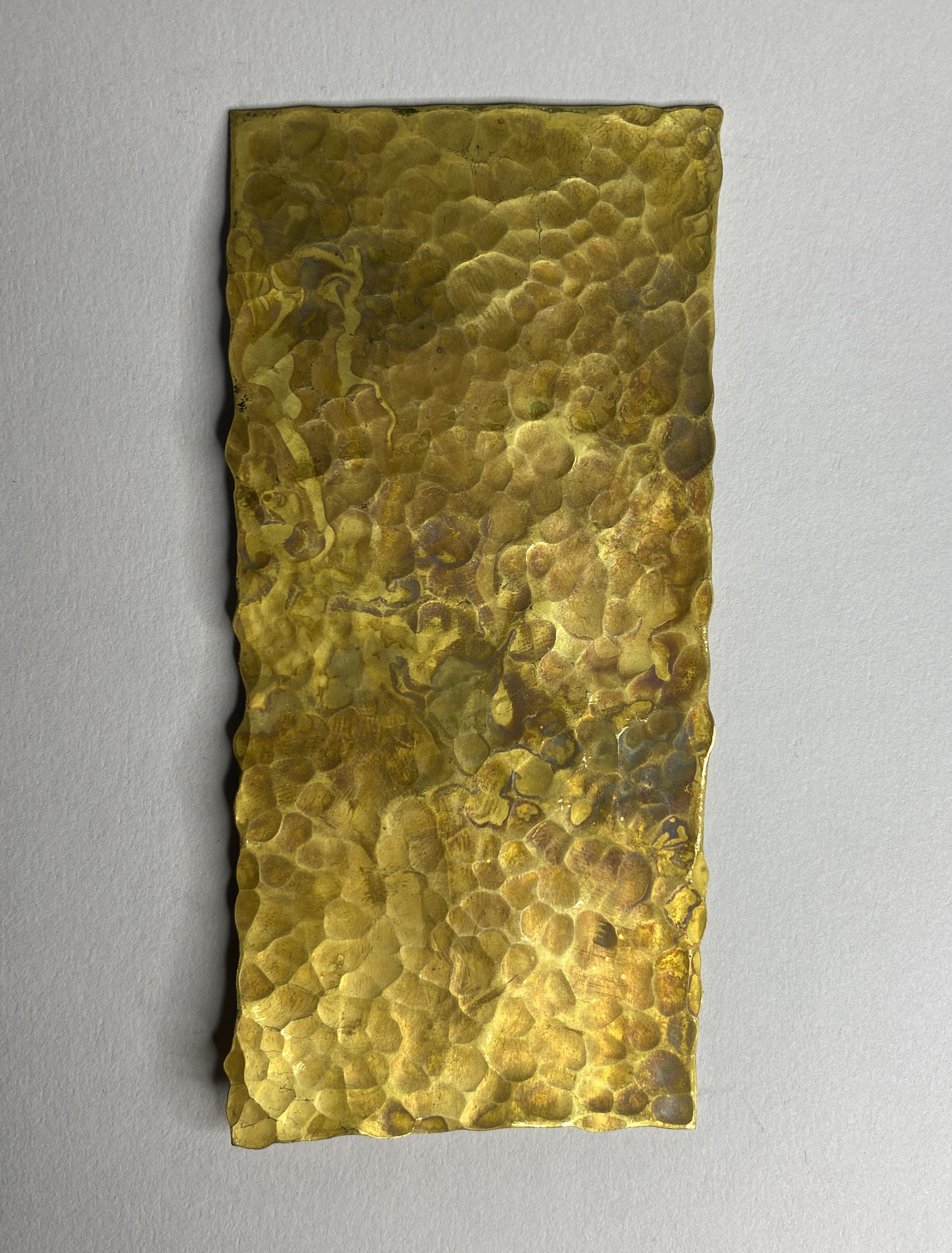
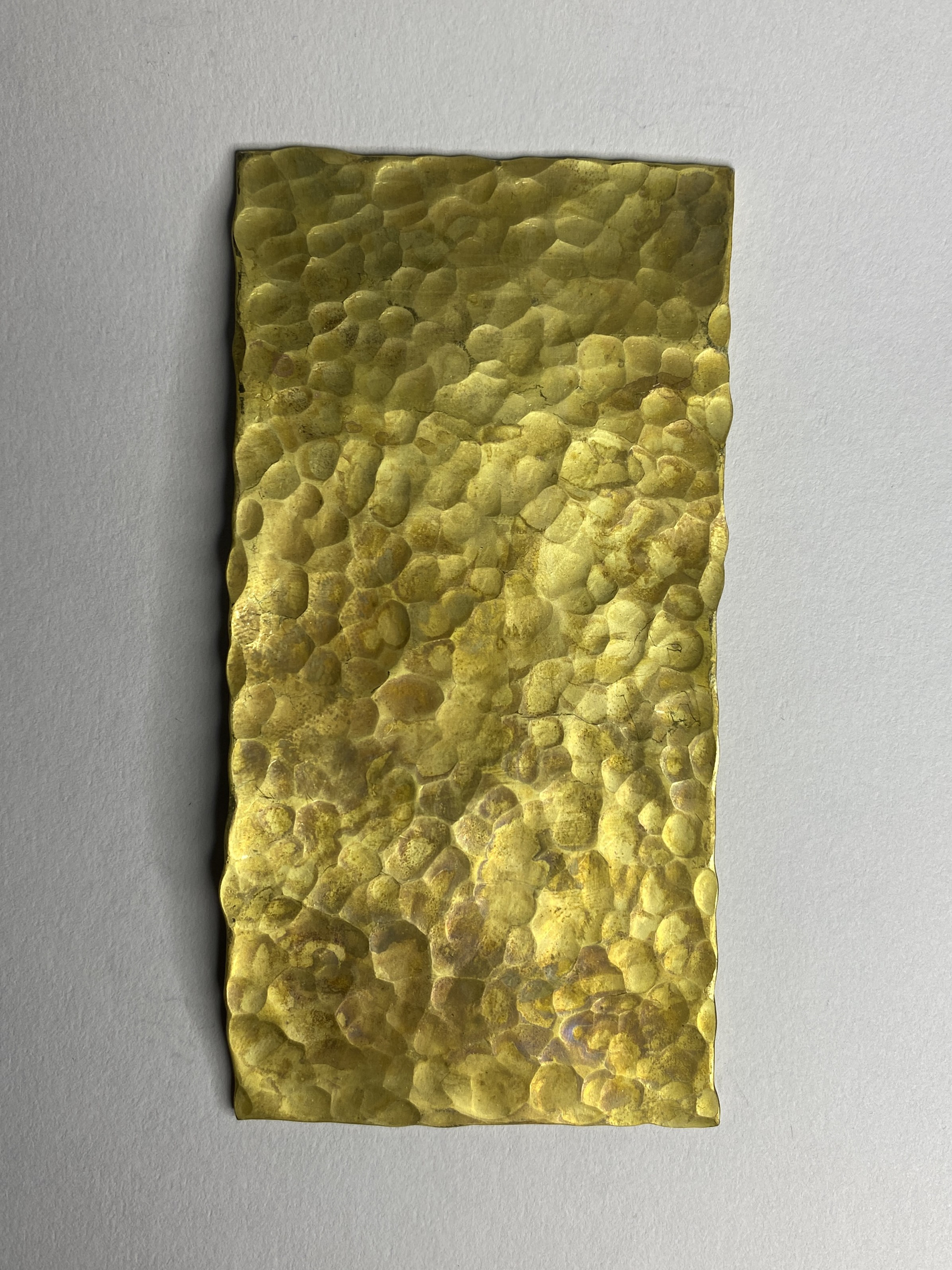
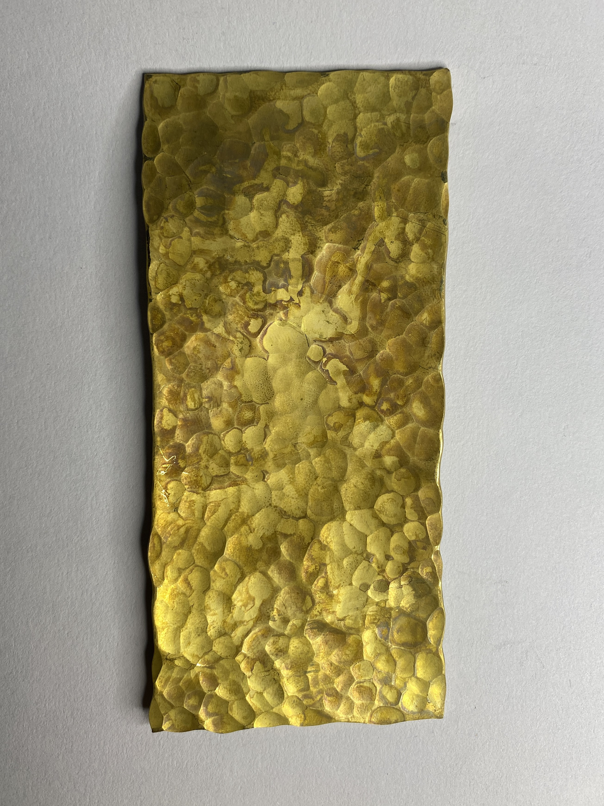
Experimenting using different shaped hammer faces to overlay marks across the surface of copper and brass. I like the simple patterns by just repeating the hammer blows in one direction rather than creating a more complex or traditional pattern.
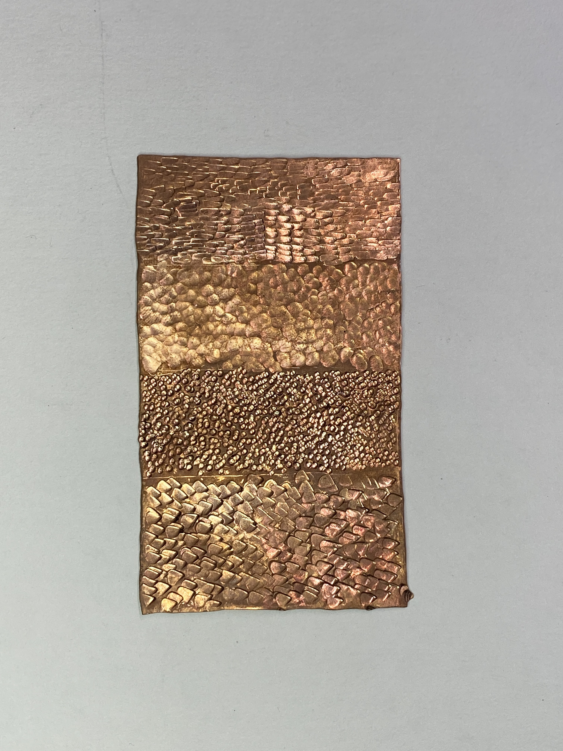
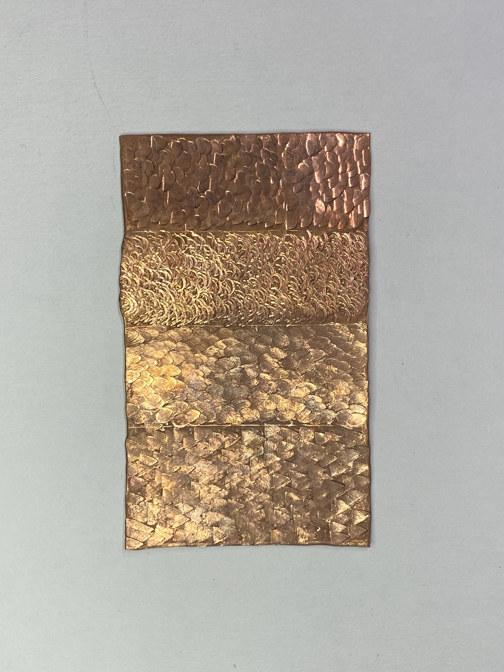
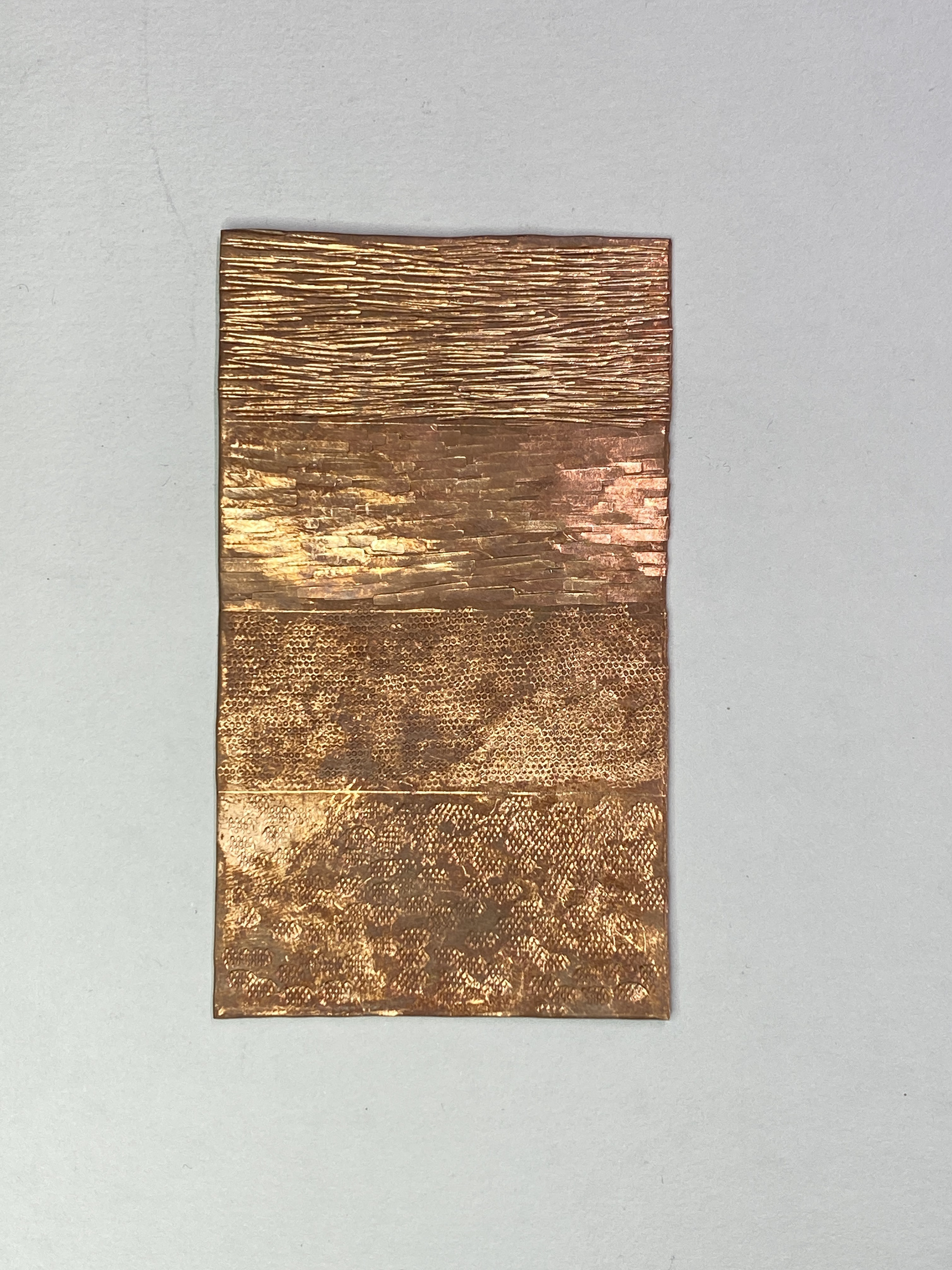
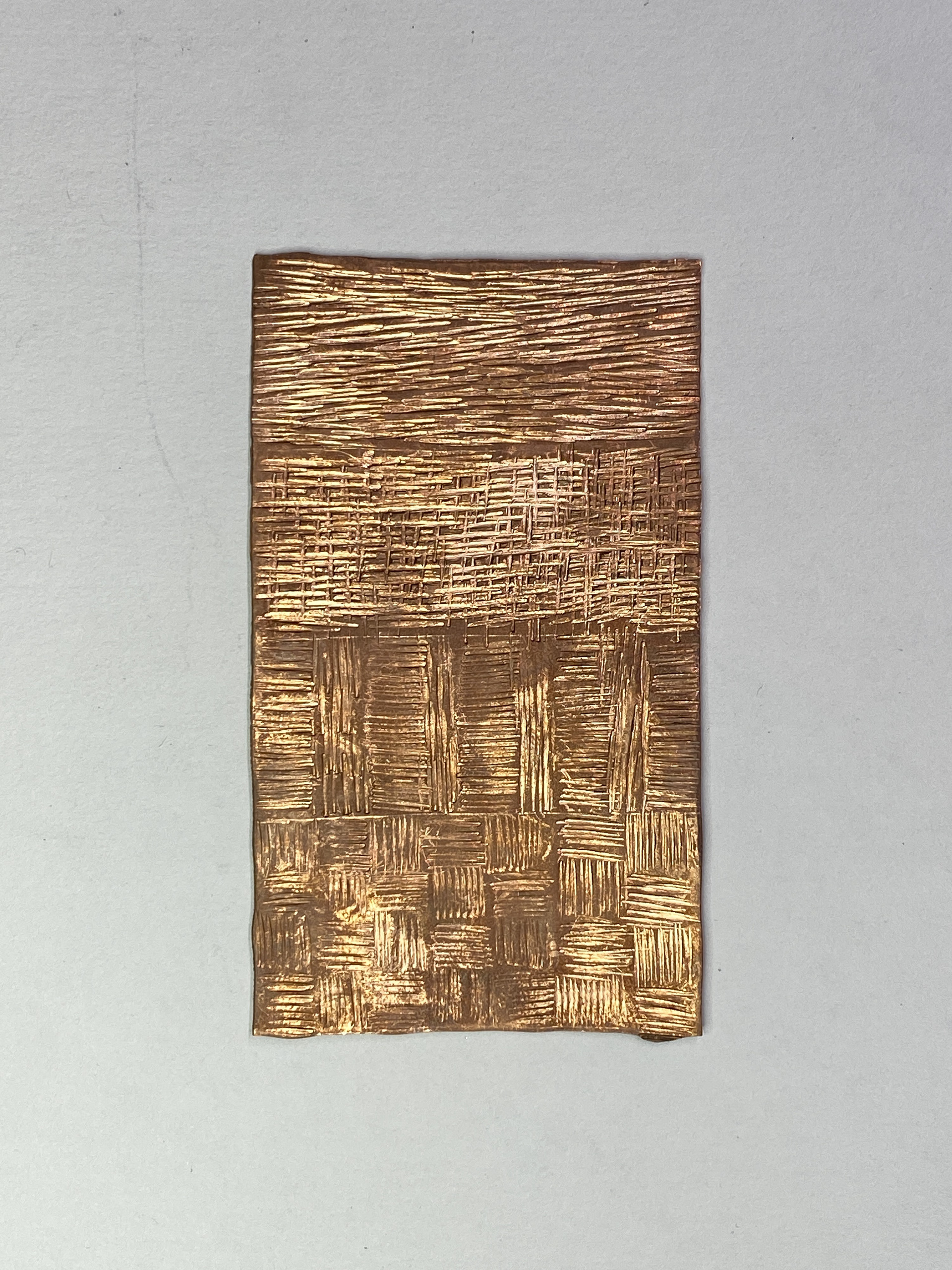
To create different shaped marks and a variety of texture, I experimented with using chasing tools. These tests will serve as a mark database so that when designing and making, I can reference the different marks I want to include in my final design.
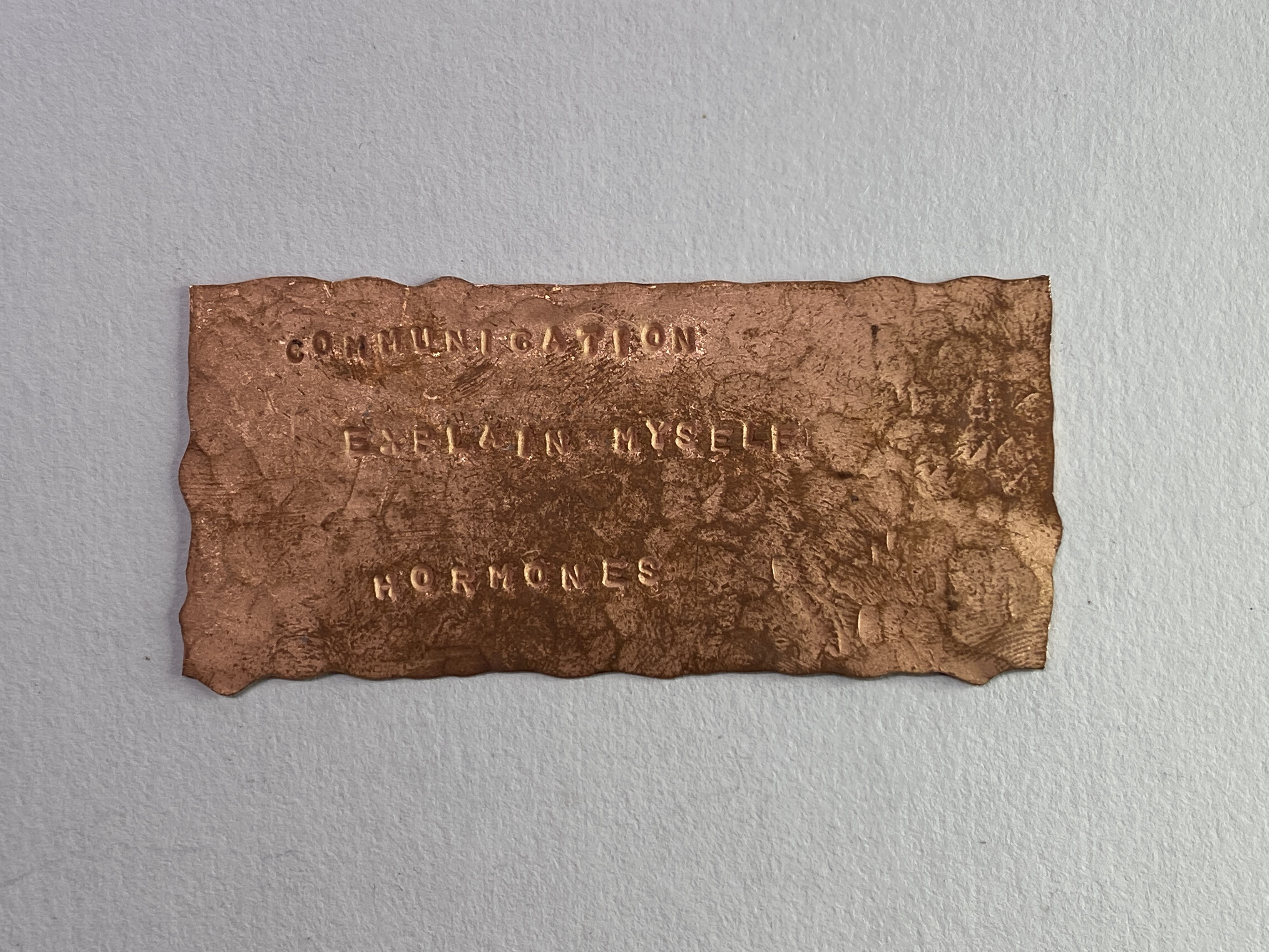
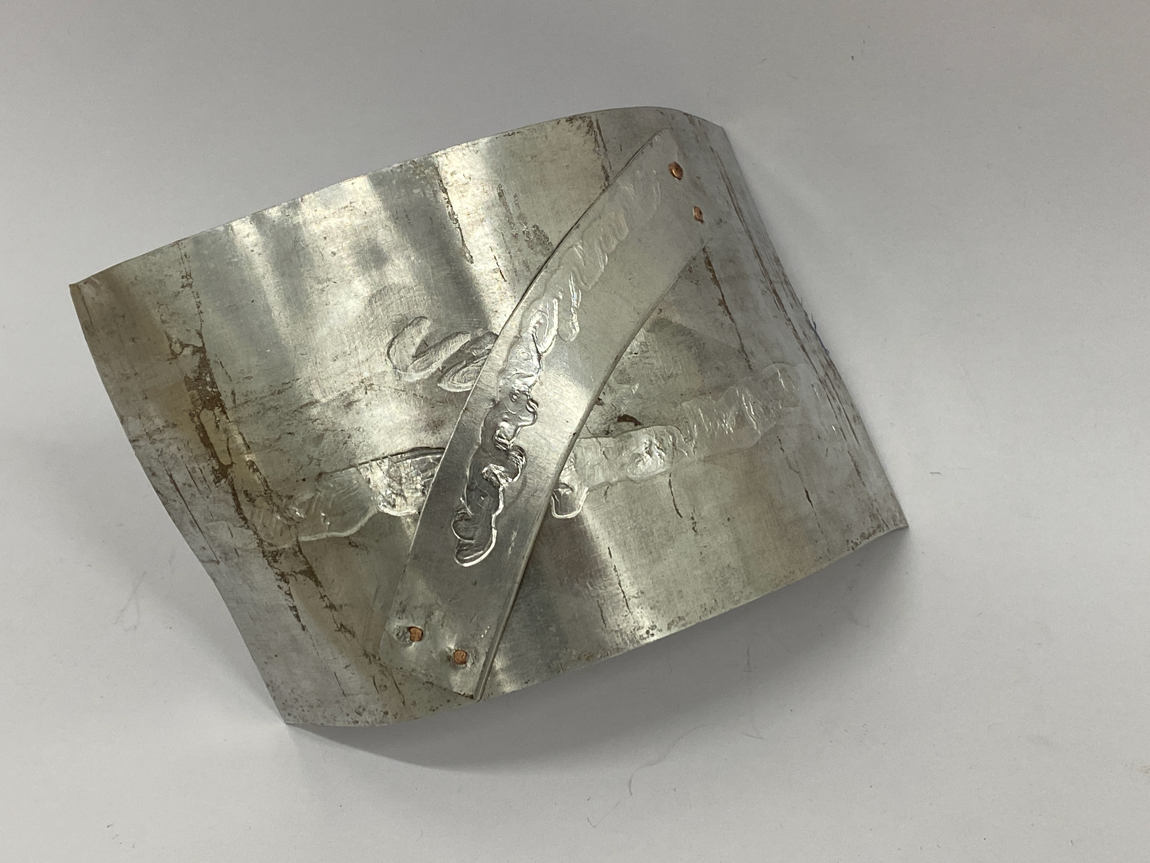
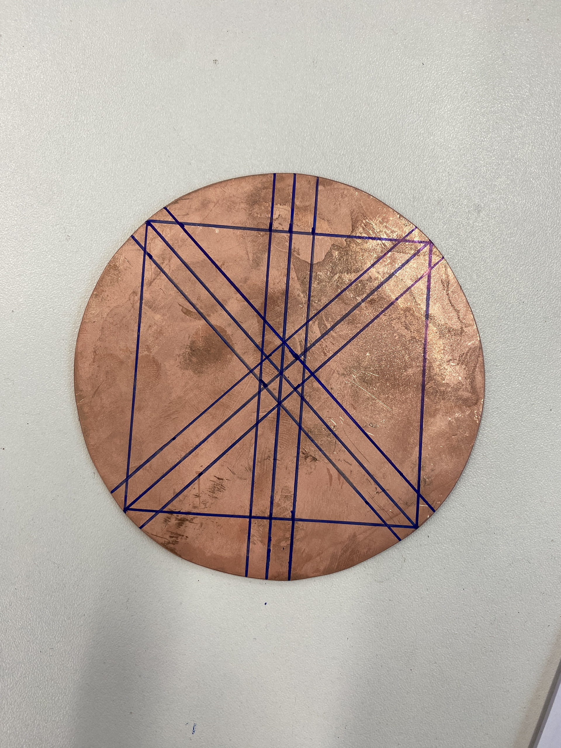
Previously I have looked at adding text onto sheet metal and then riveting it onto a back plate which creates clarity and emphasises the text. I like this as it increases the vulnerability of the wearer. However, I want to explore varying the visibility of the text and adding it into the base sheet metal rather than always attaching the text plate on. Therefore, I tested texturing one side of copper using a ball peen hammer and then stamping in the text on the other.
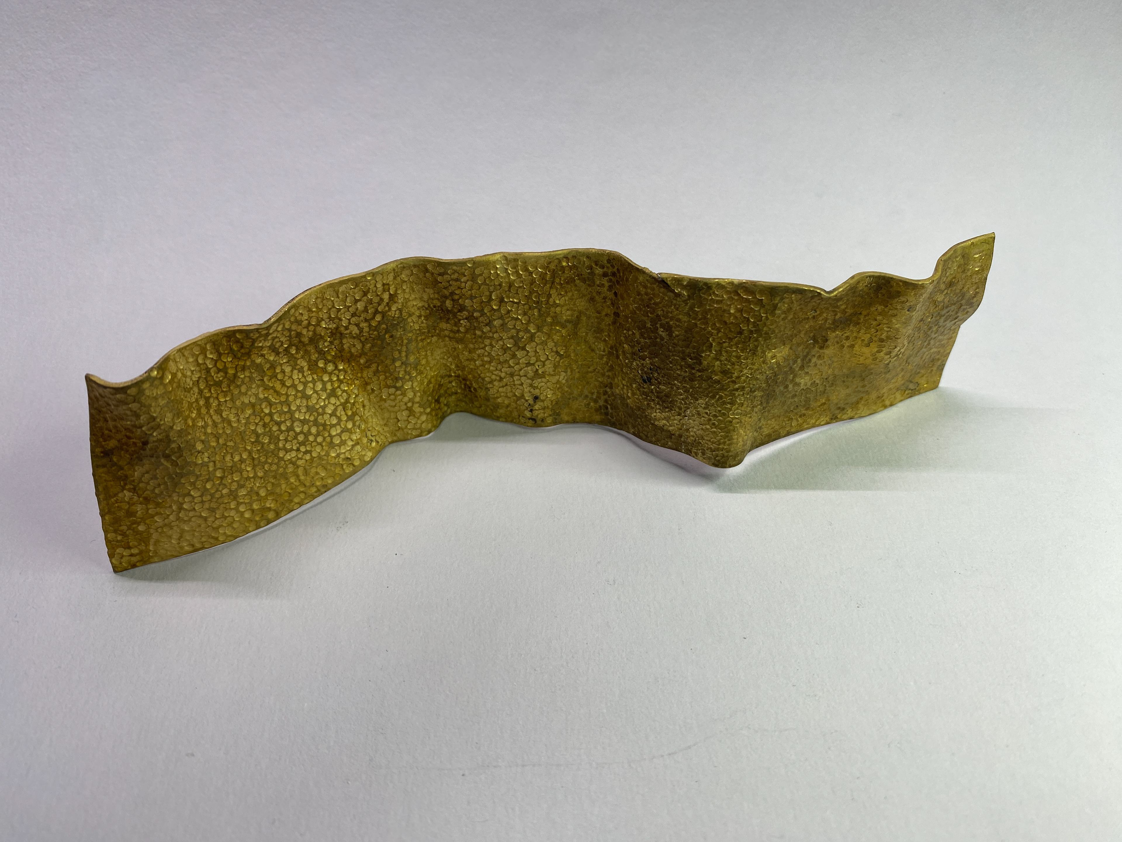
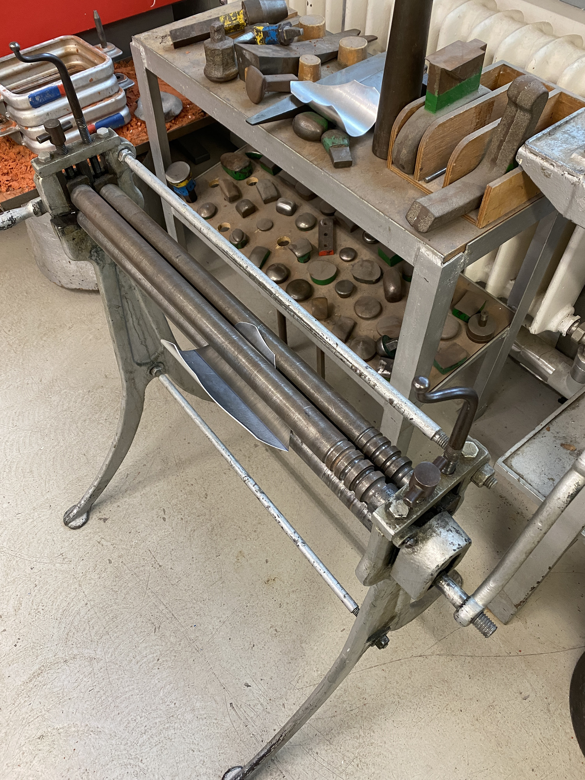
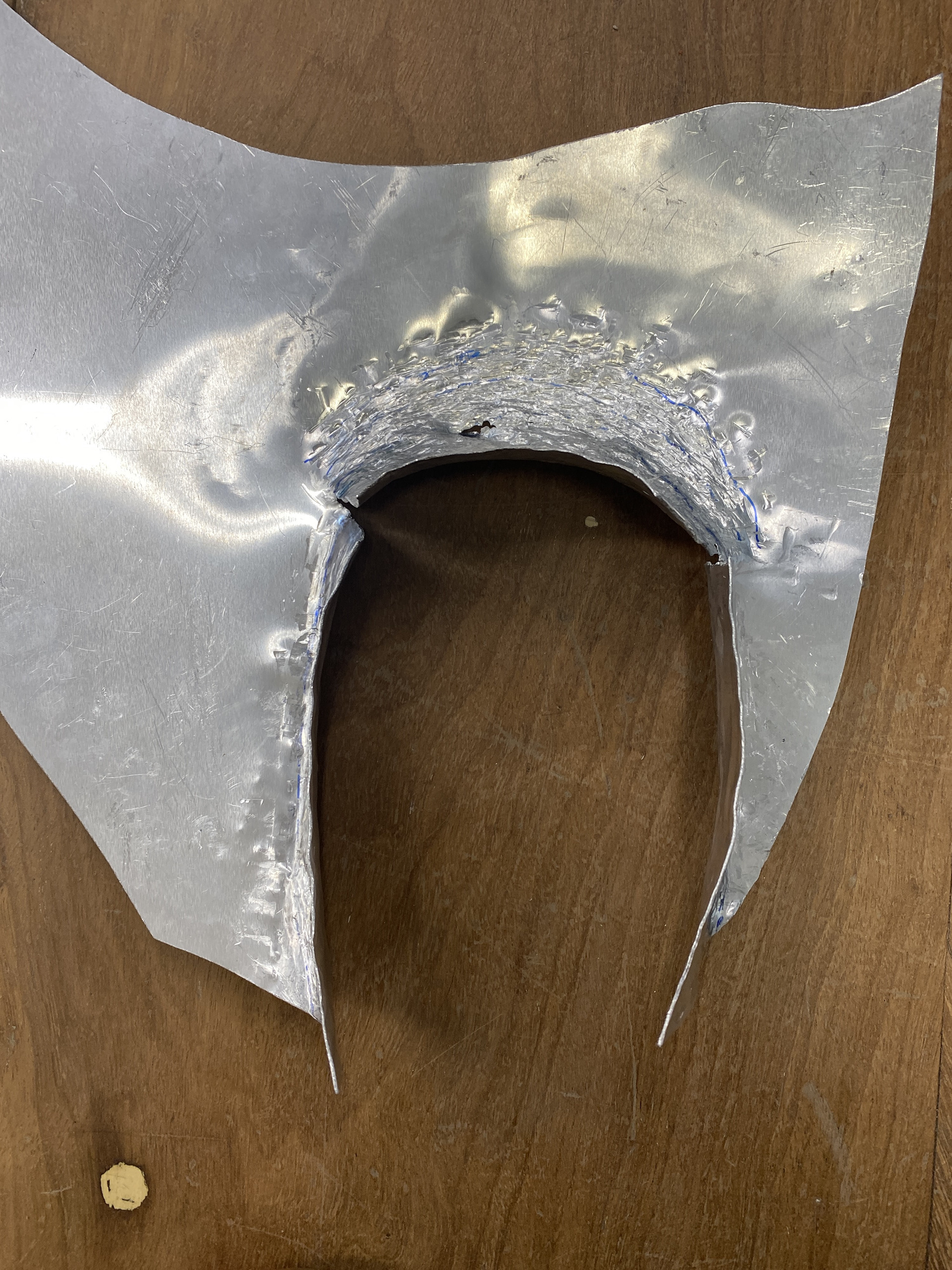
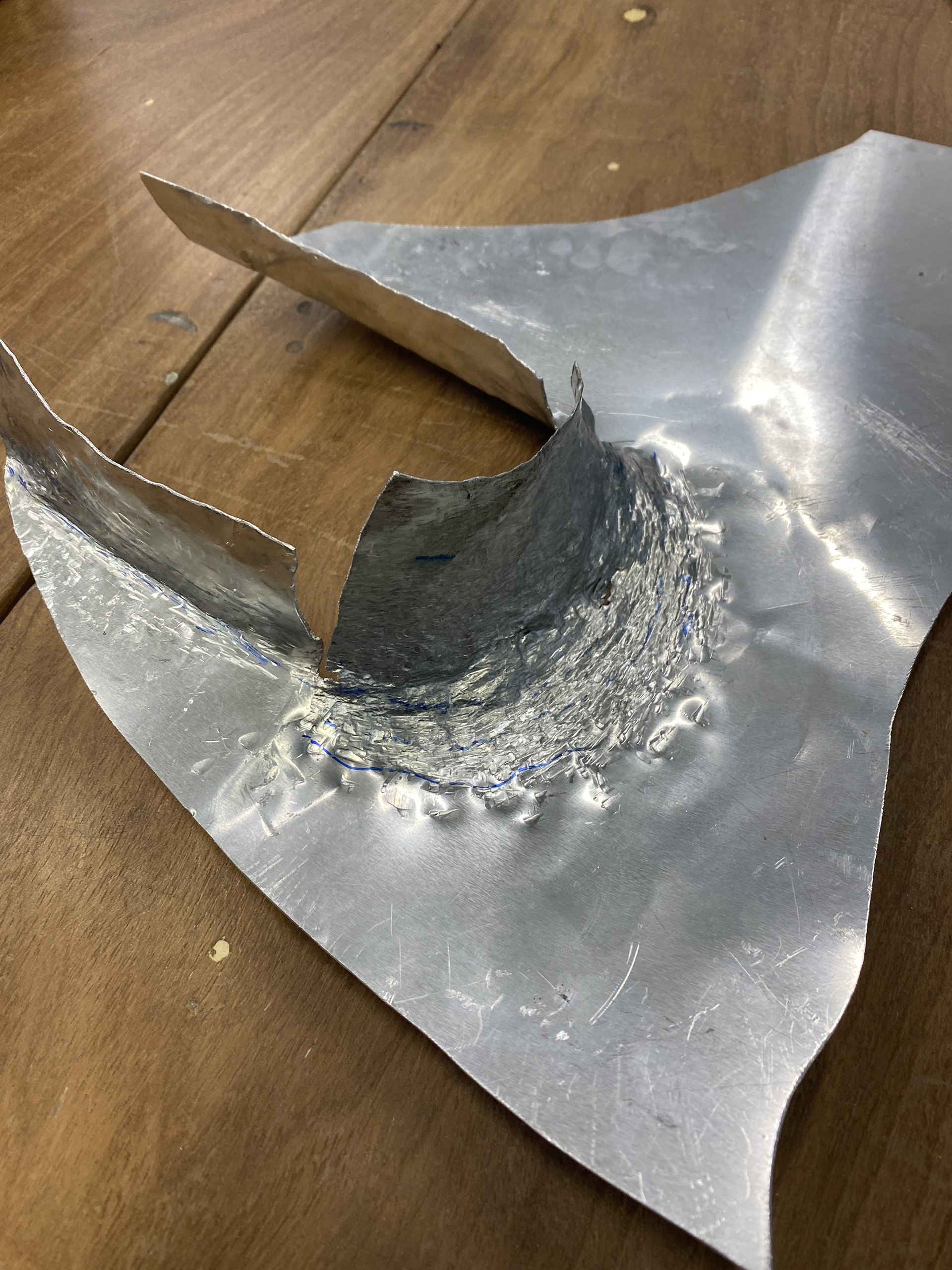
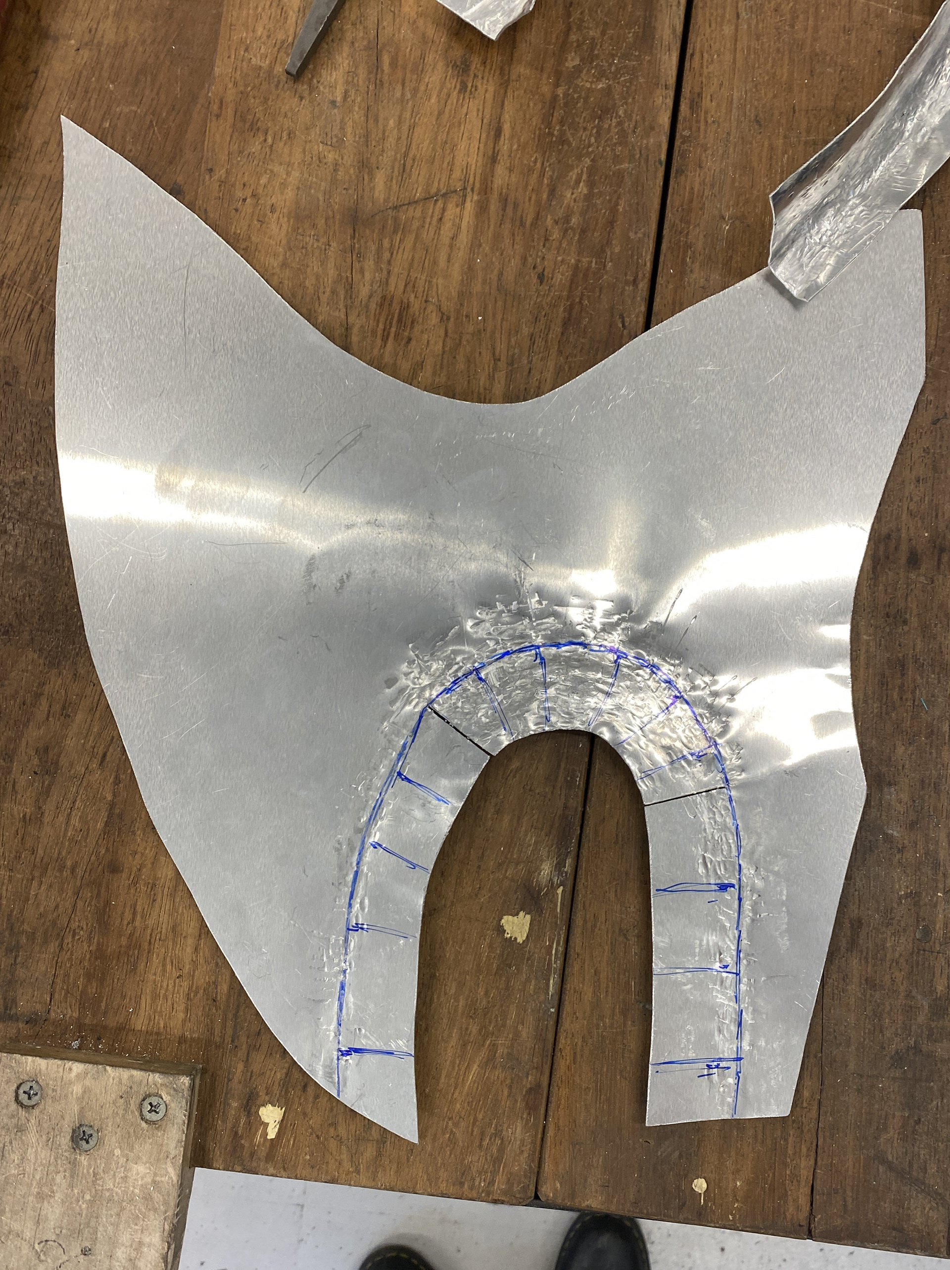
Practising texturing larger sheets and creating a fluid form. I found that when texturing using the chasing tools, it was easiest to hold down the work with tape onto the anvil so that I only had to focus on holding the chasing tool in the correct position. Also, using a rubber mallet was useful to flatten the work as it tends to fold up when texturing, making it harder to position the tools.
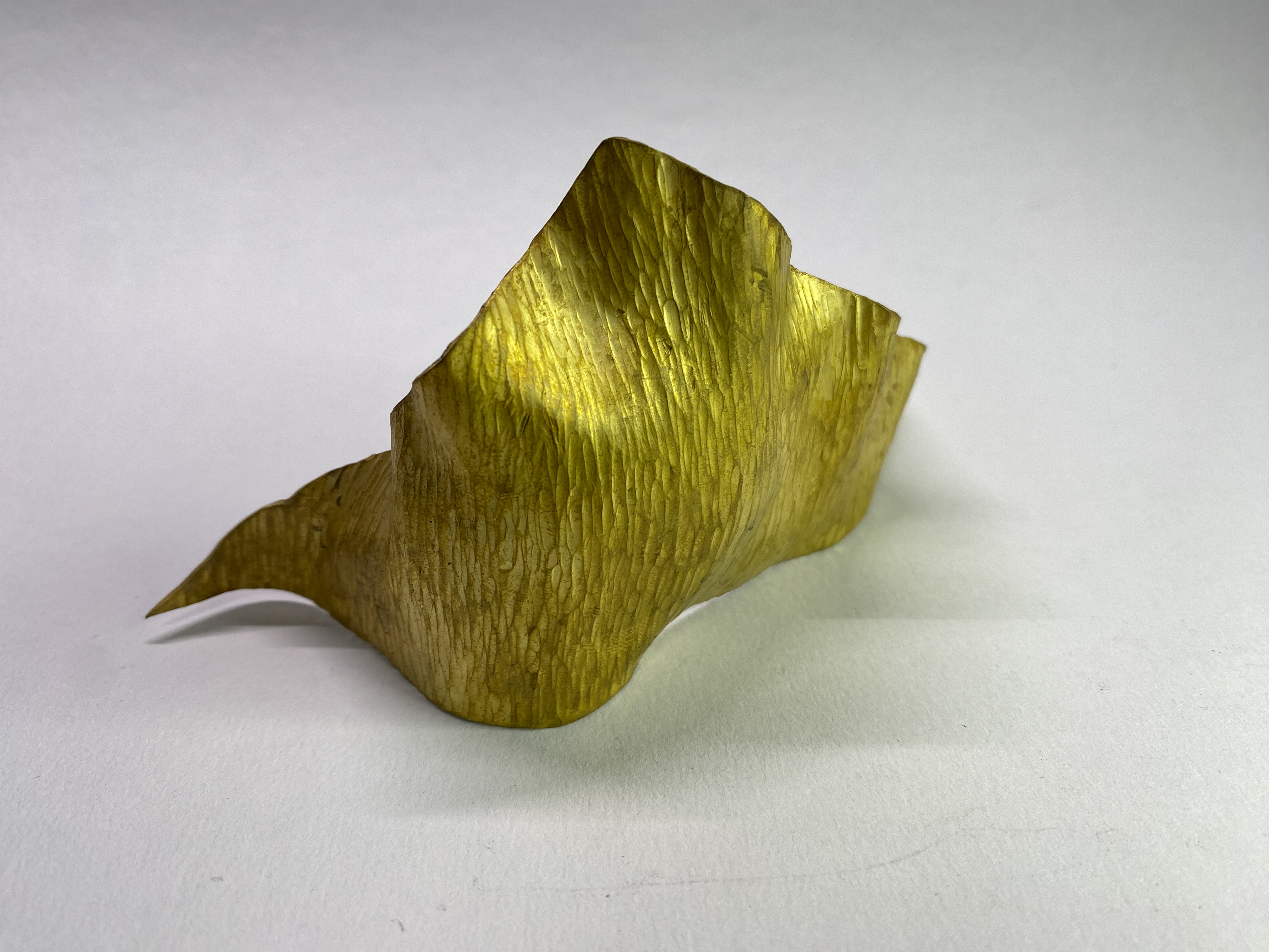
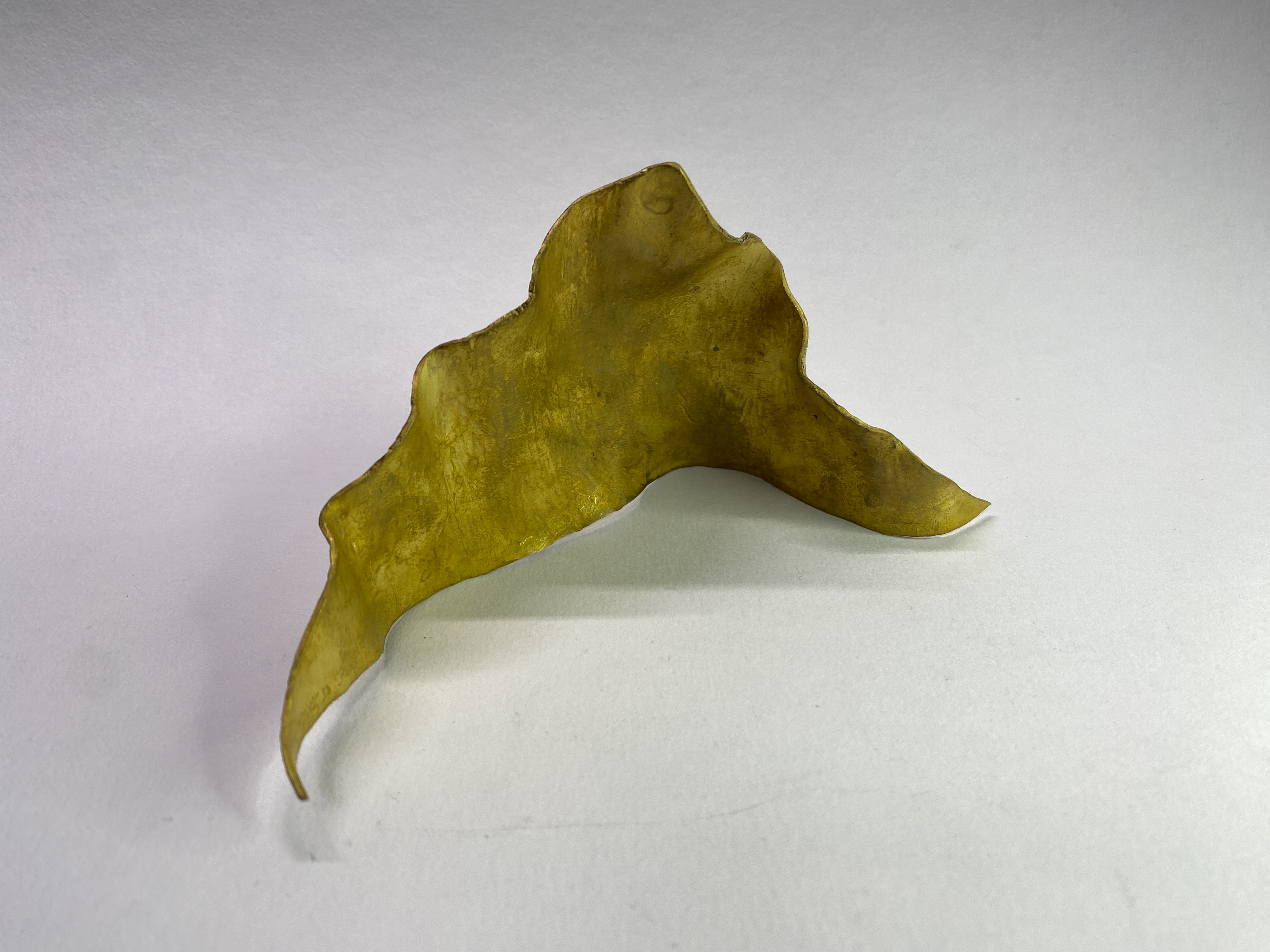
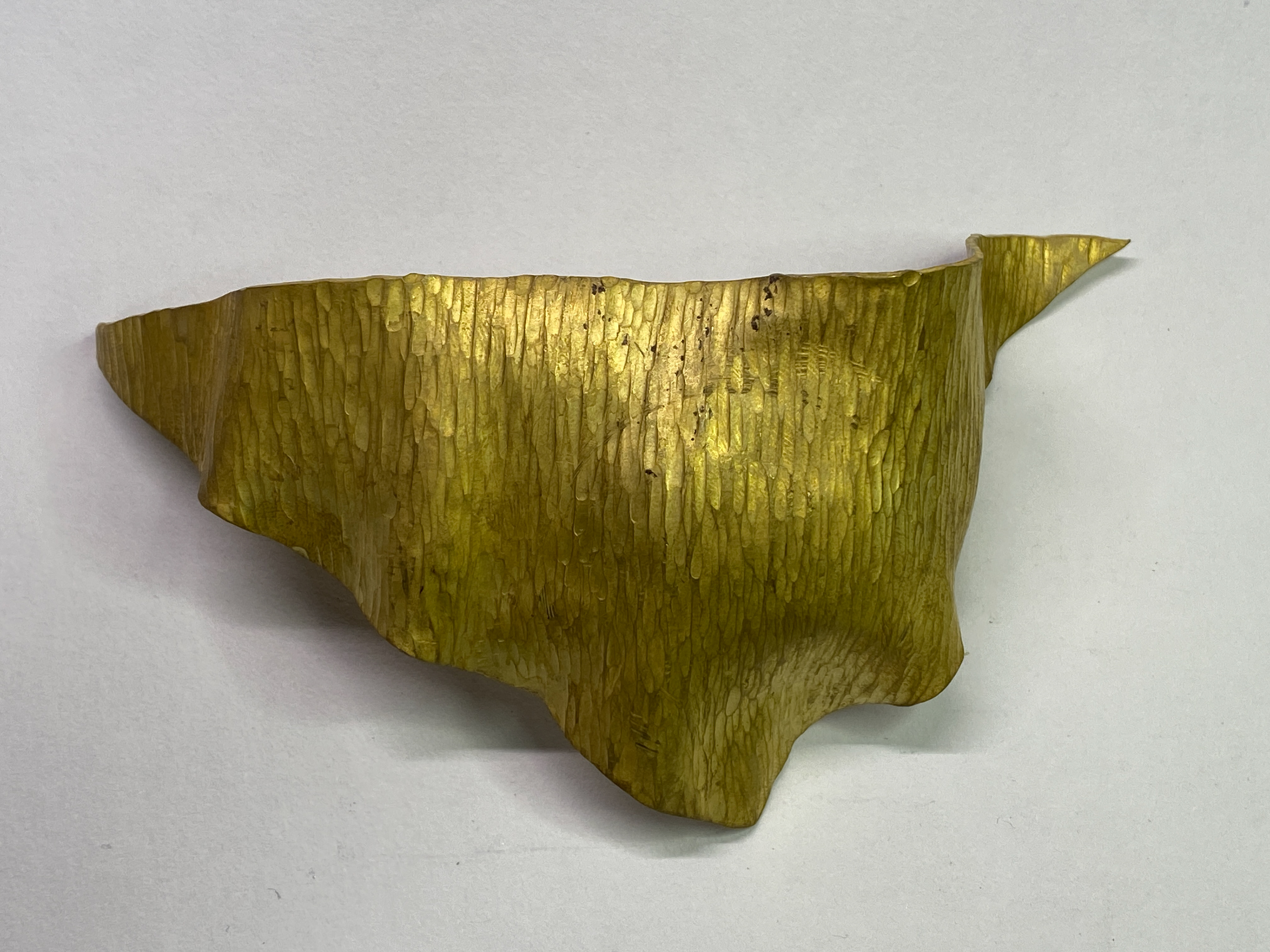
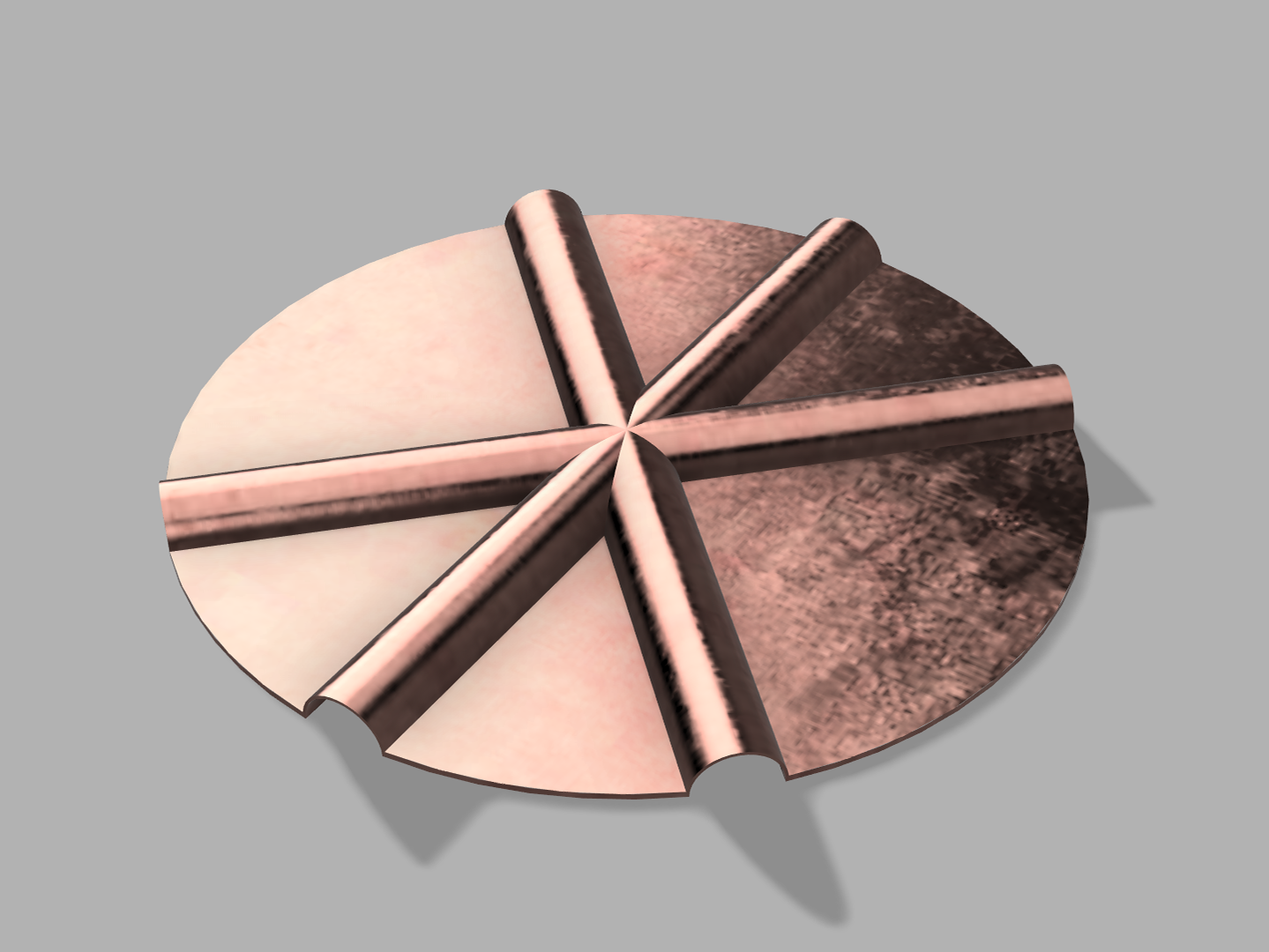
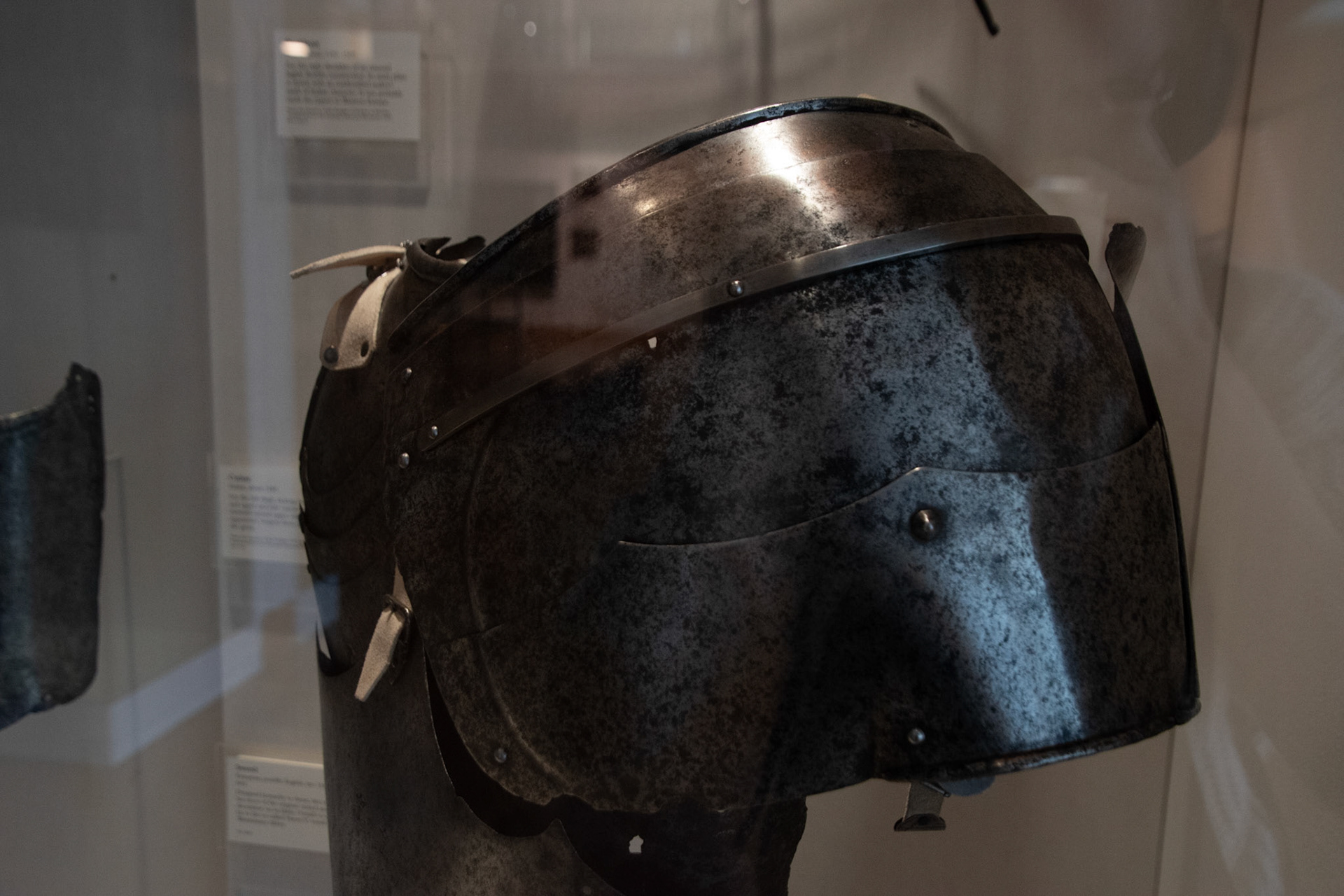
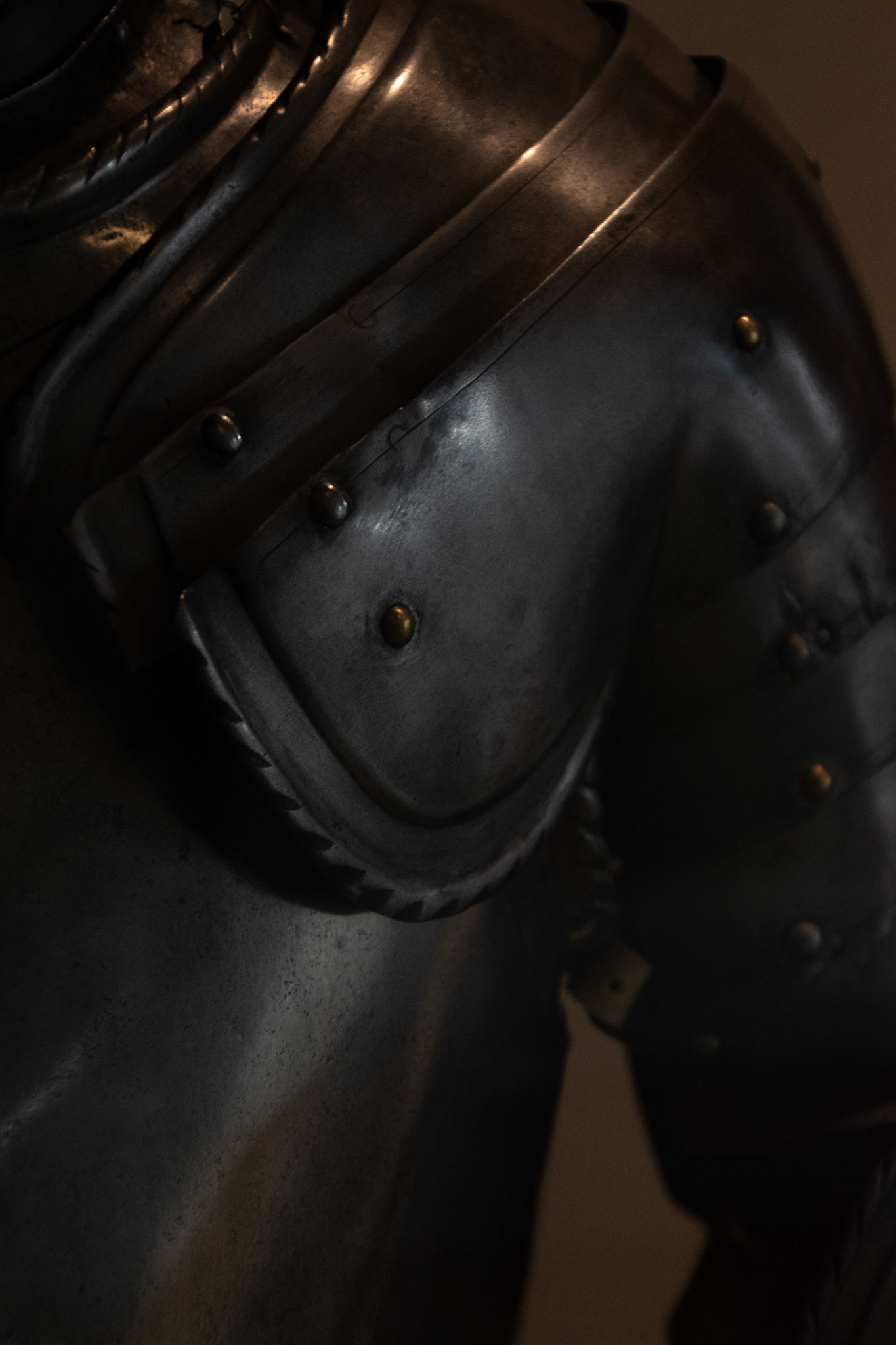
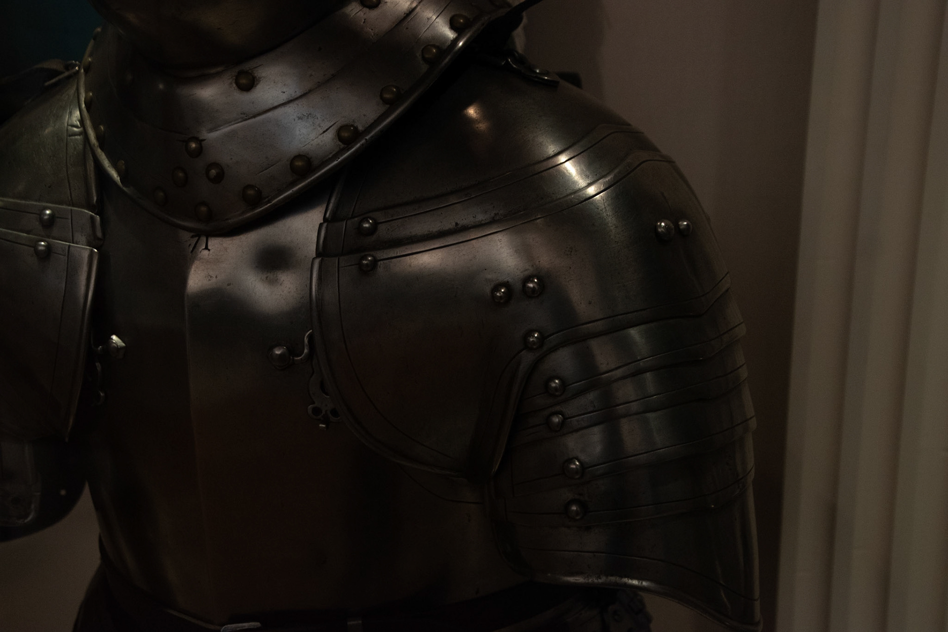
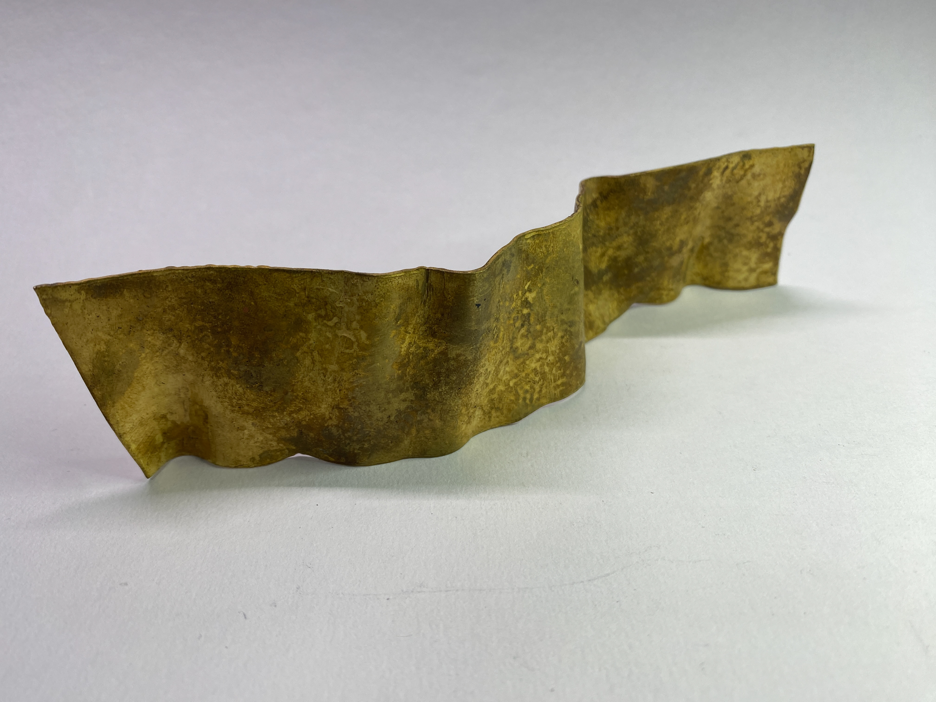
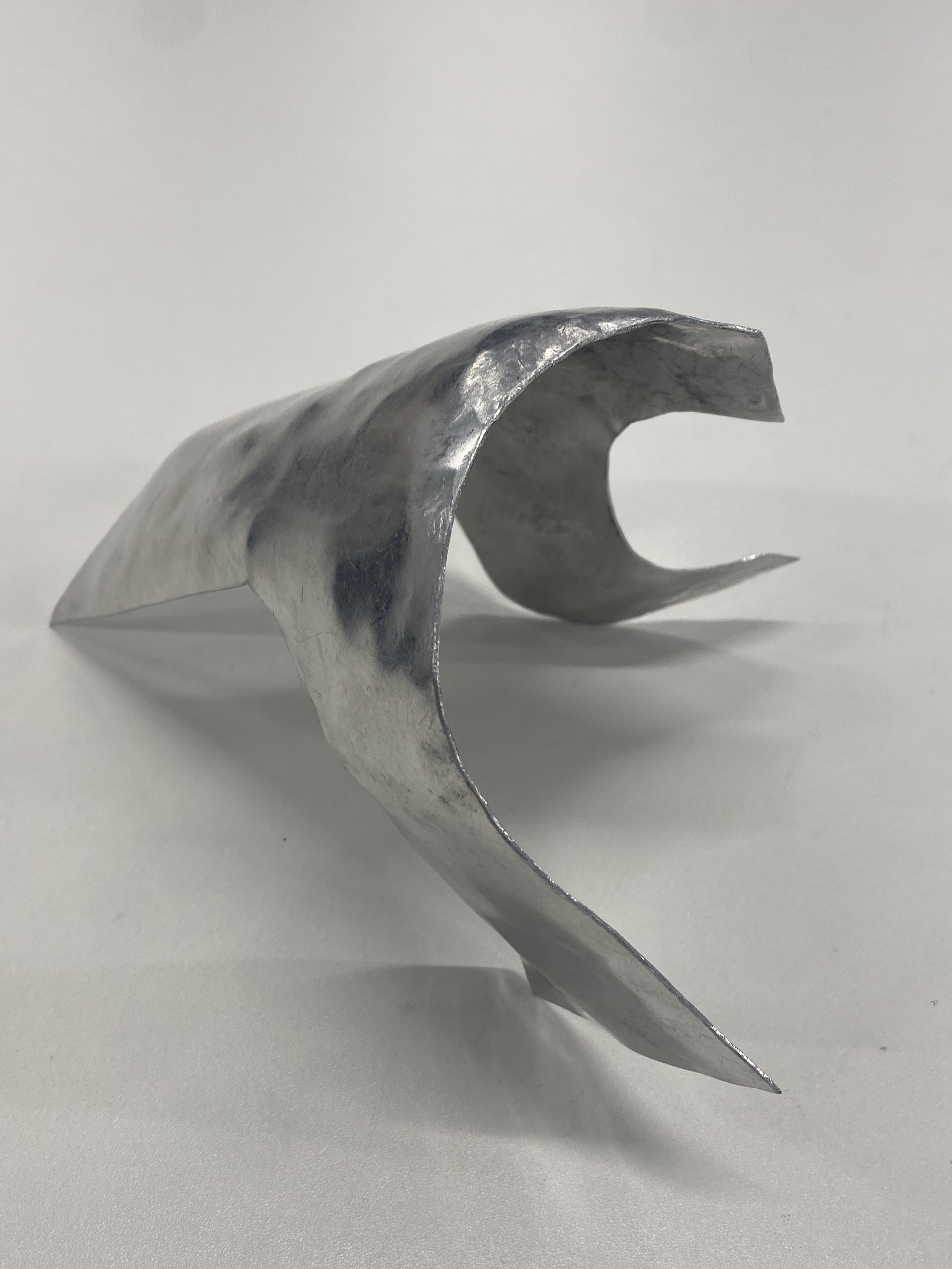
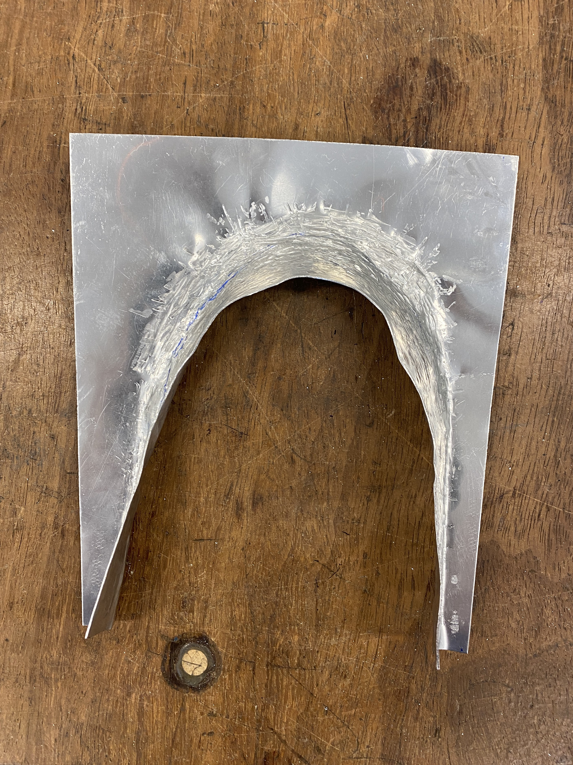
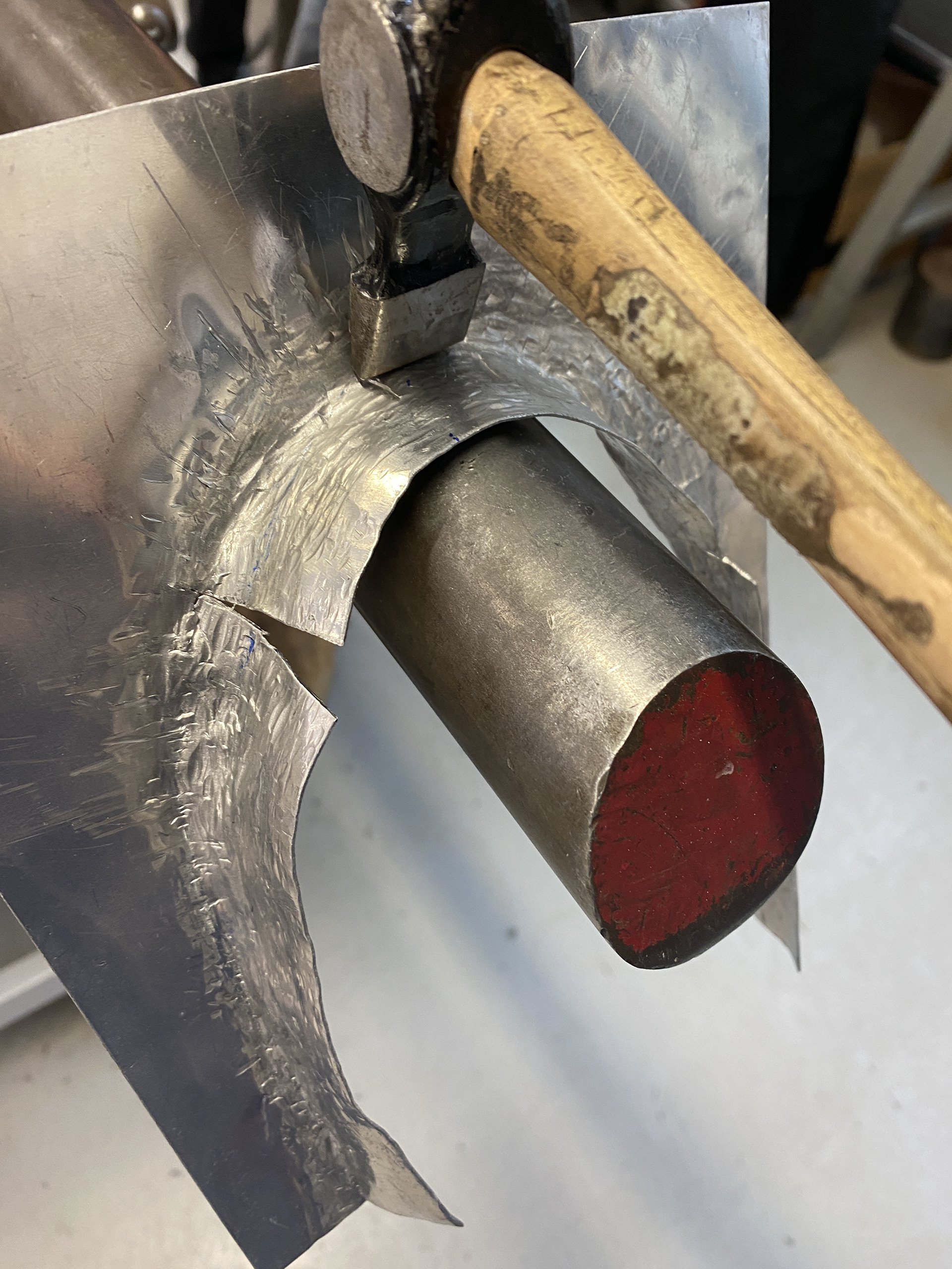
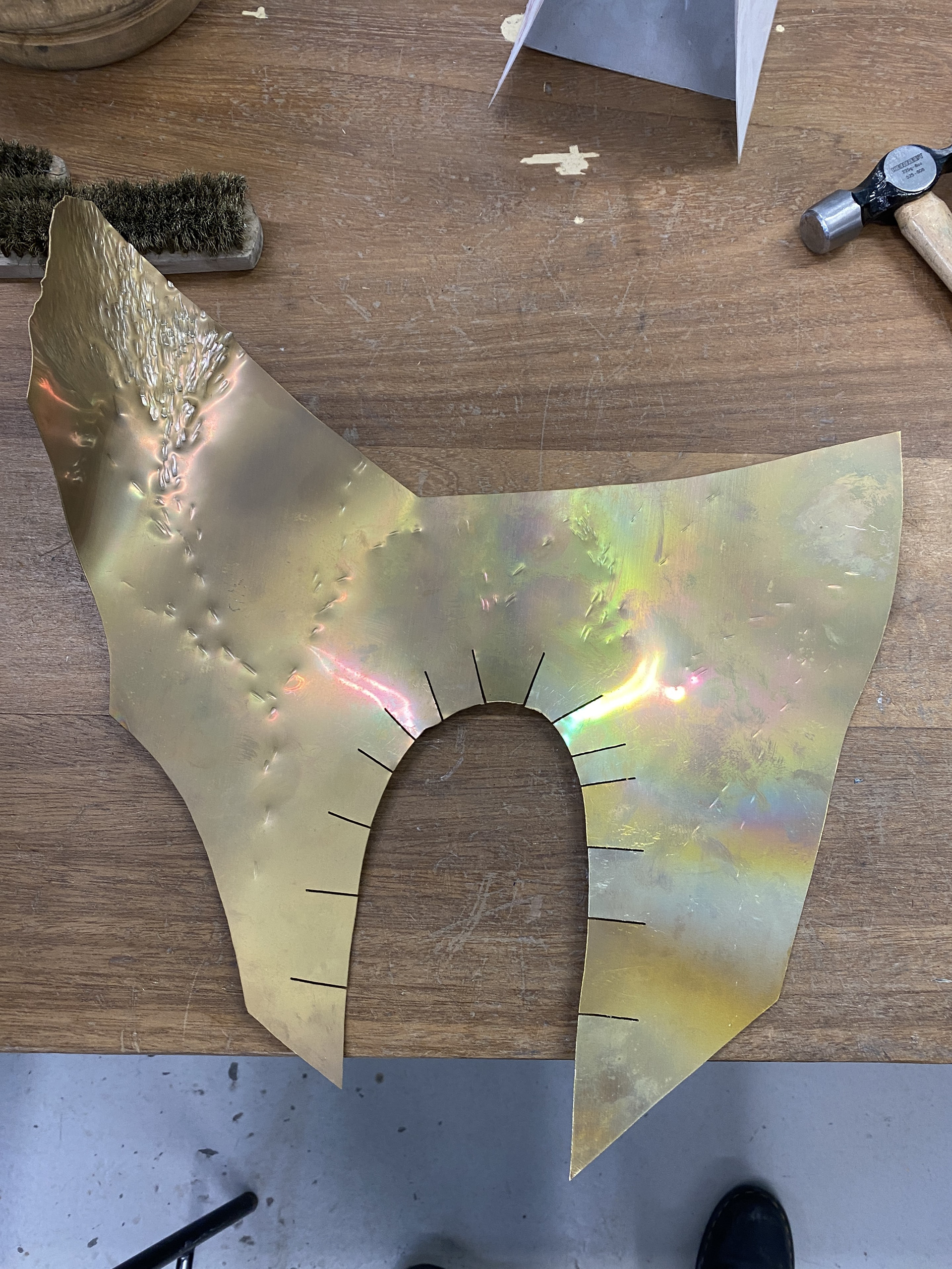
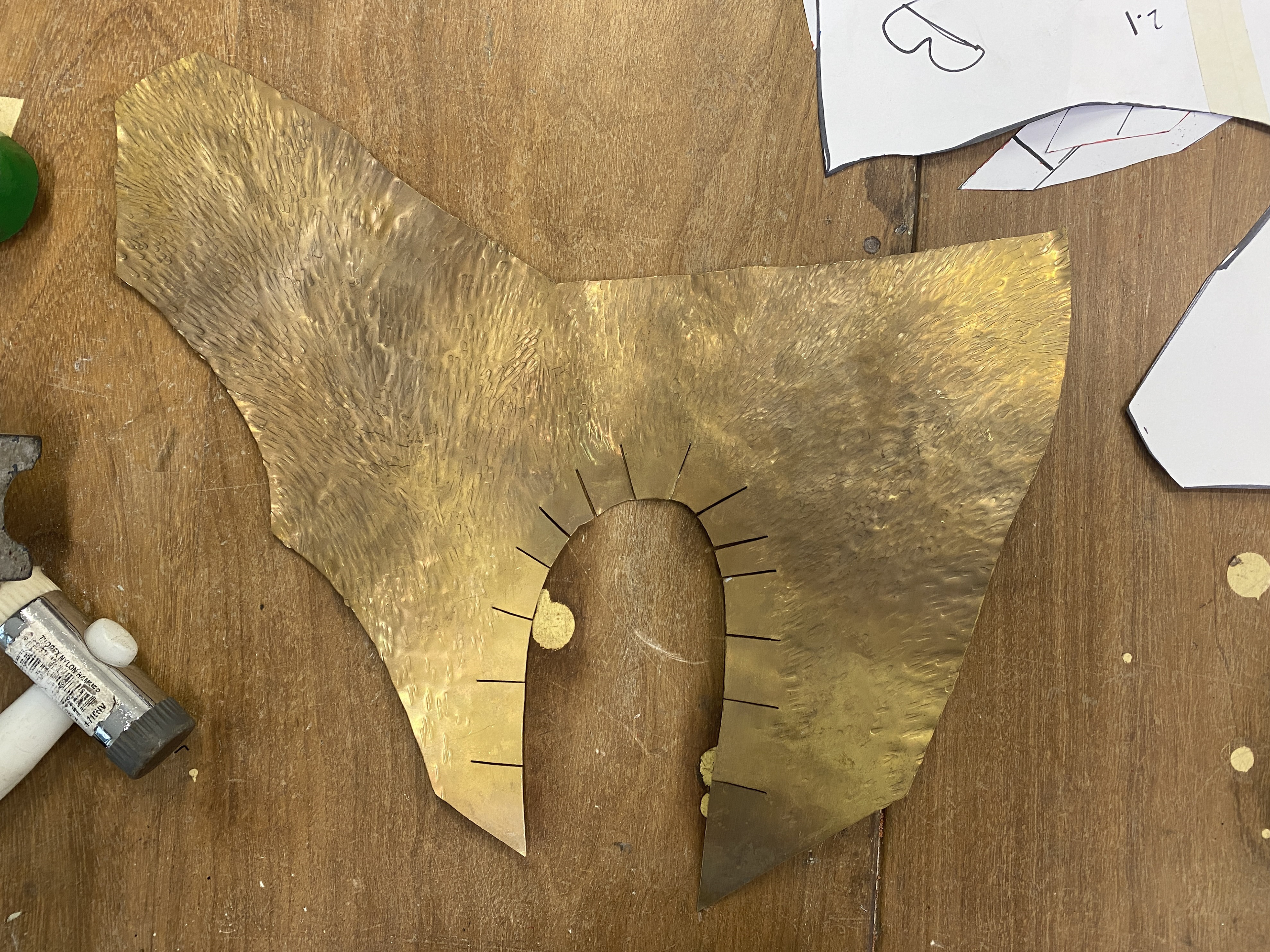
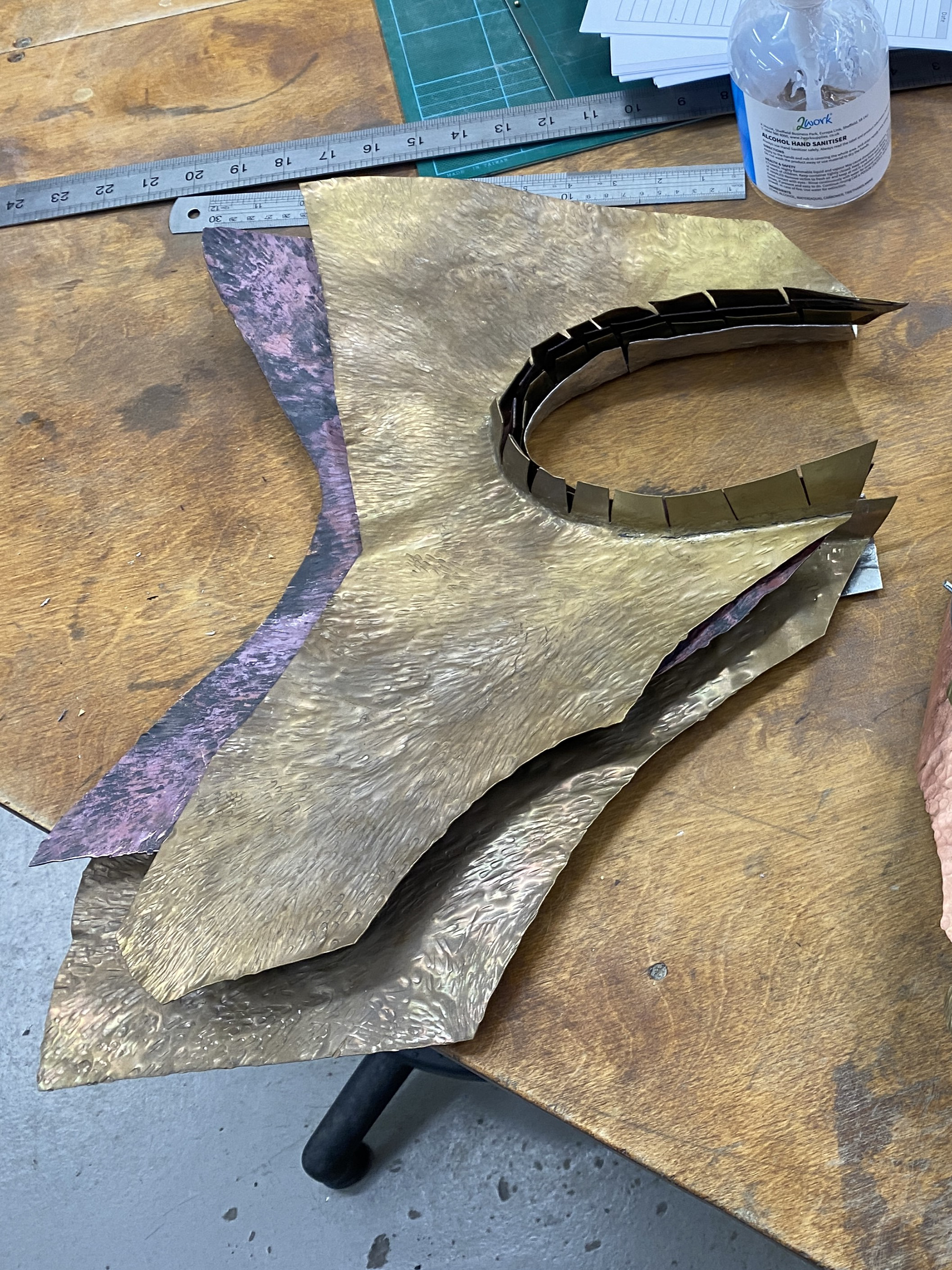
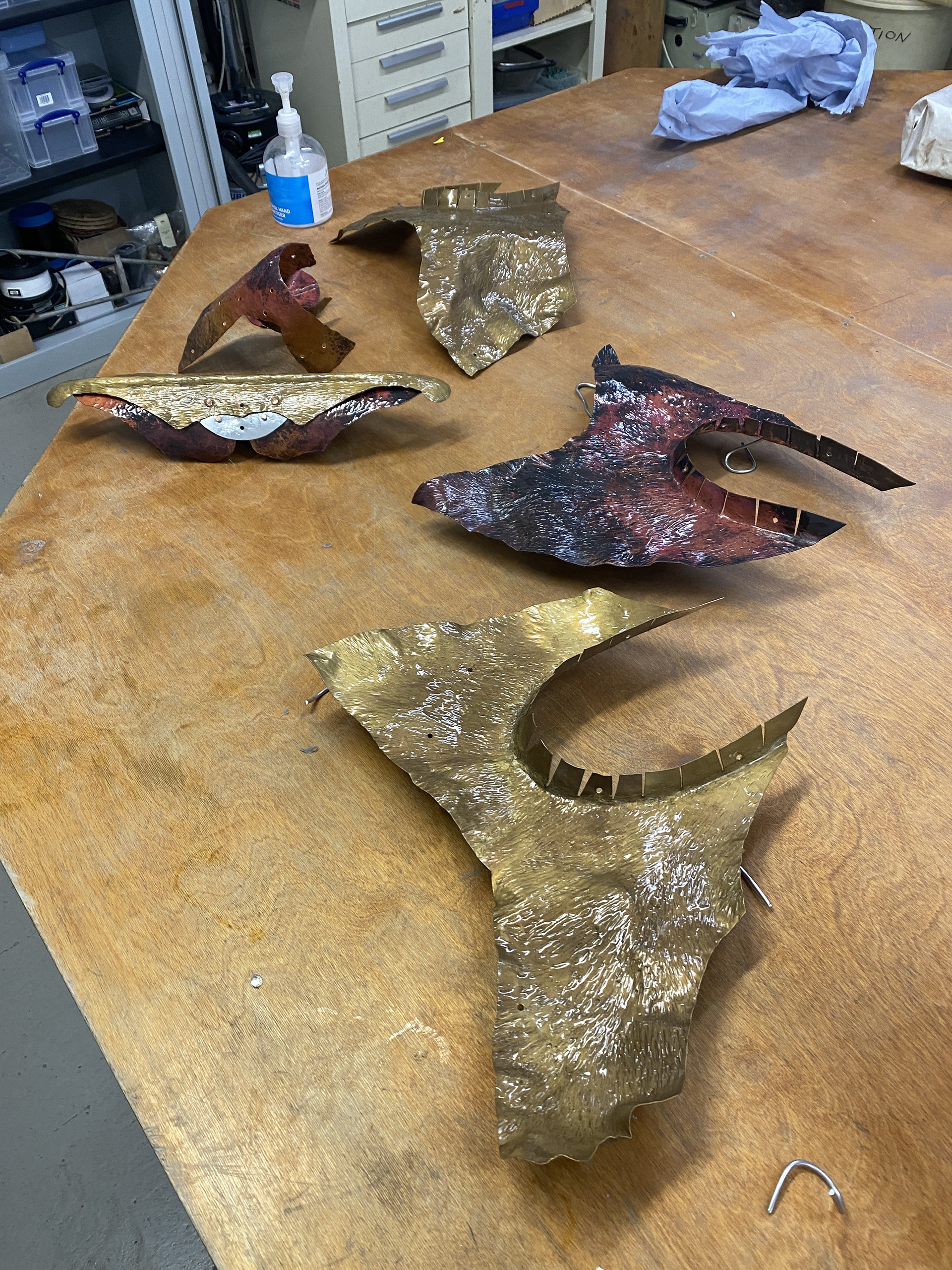
Continuing the texturing process with a riveting hammer and introducing more concaved and convex forms using doming blocks and swage blocks. Through doing this, I discovered the importance of continuous annealing the work to make more natural adjustments. Moreover, annealing part of the work allowed for smaller adjustments whilst keeping the rest of the piece's form rigid.
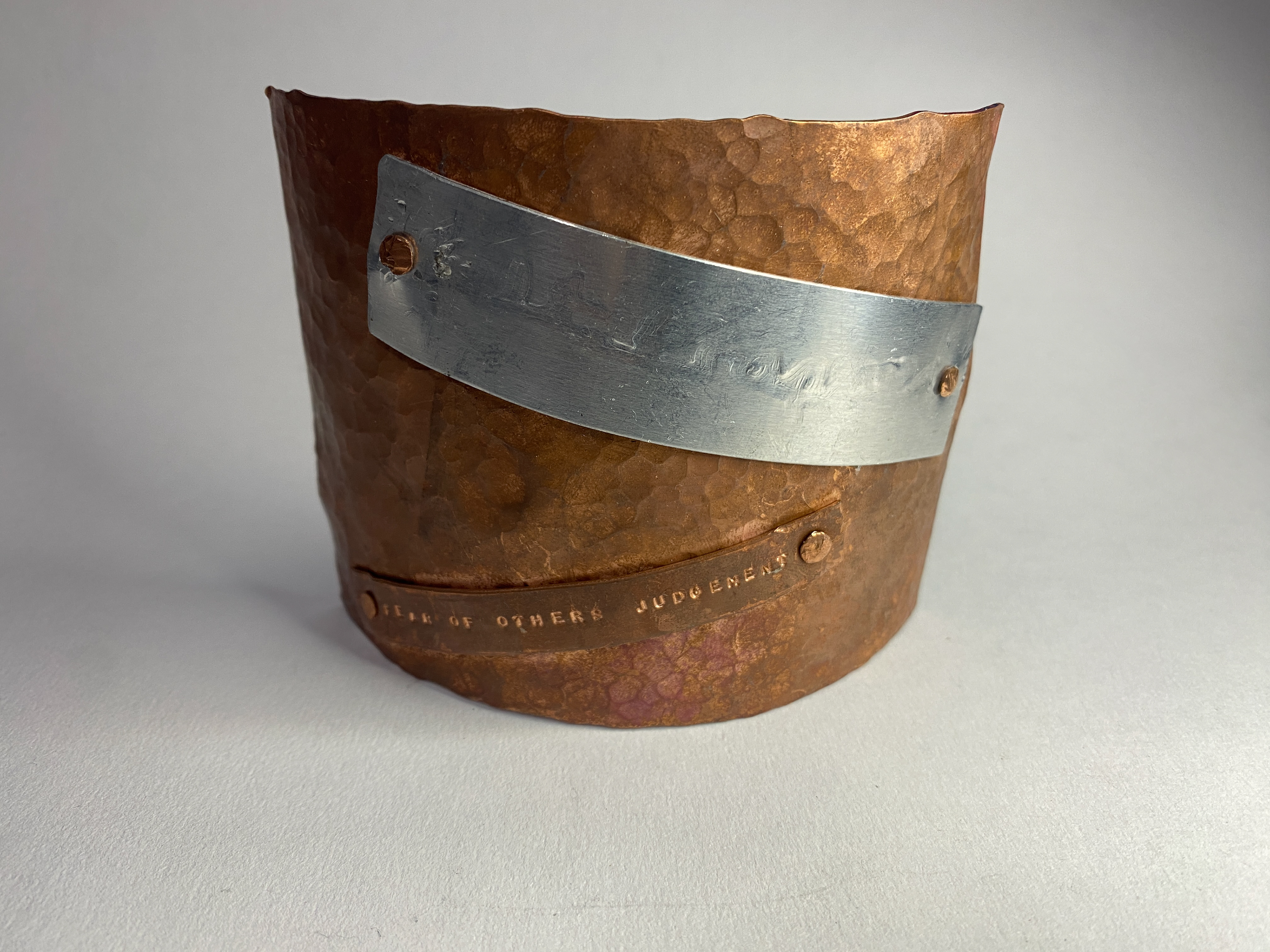
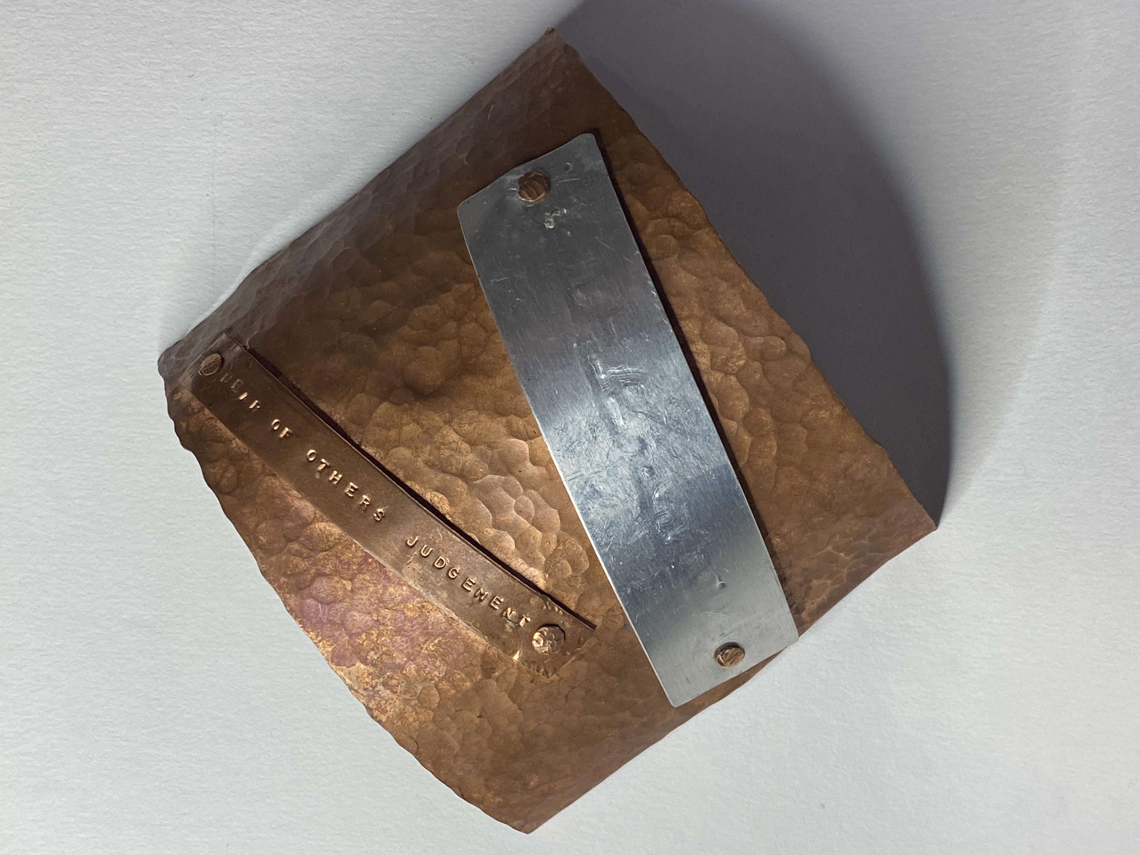
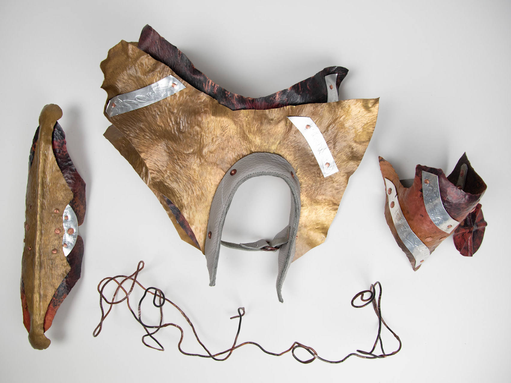
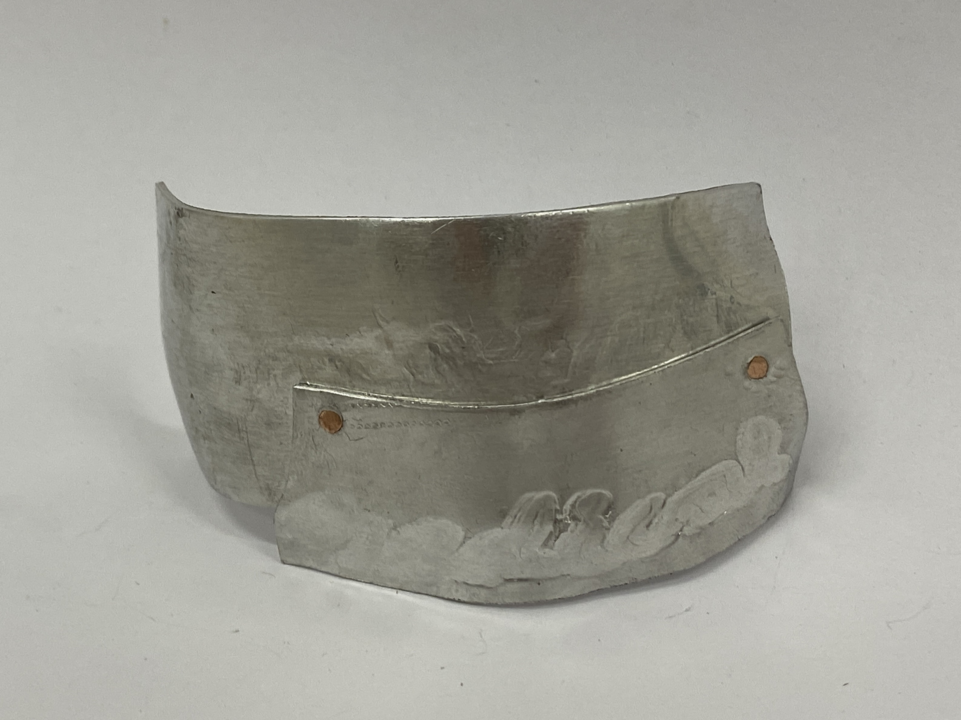
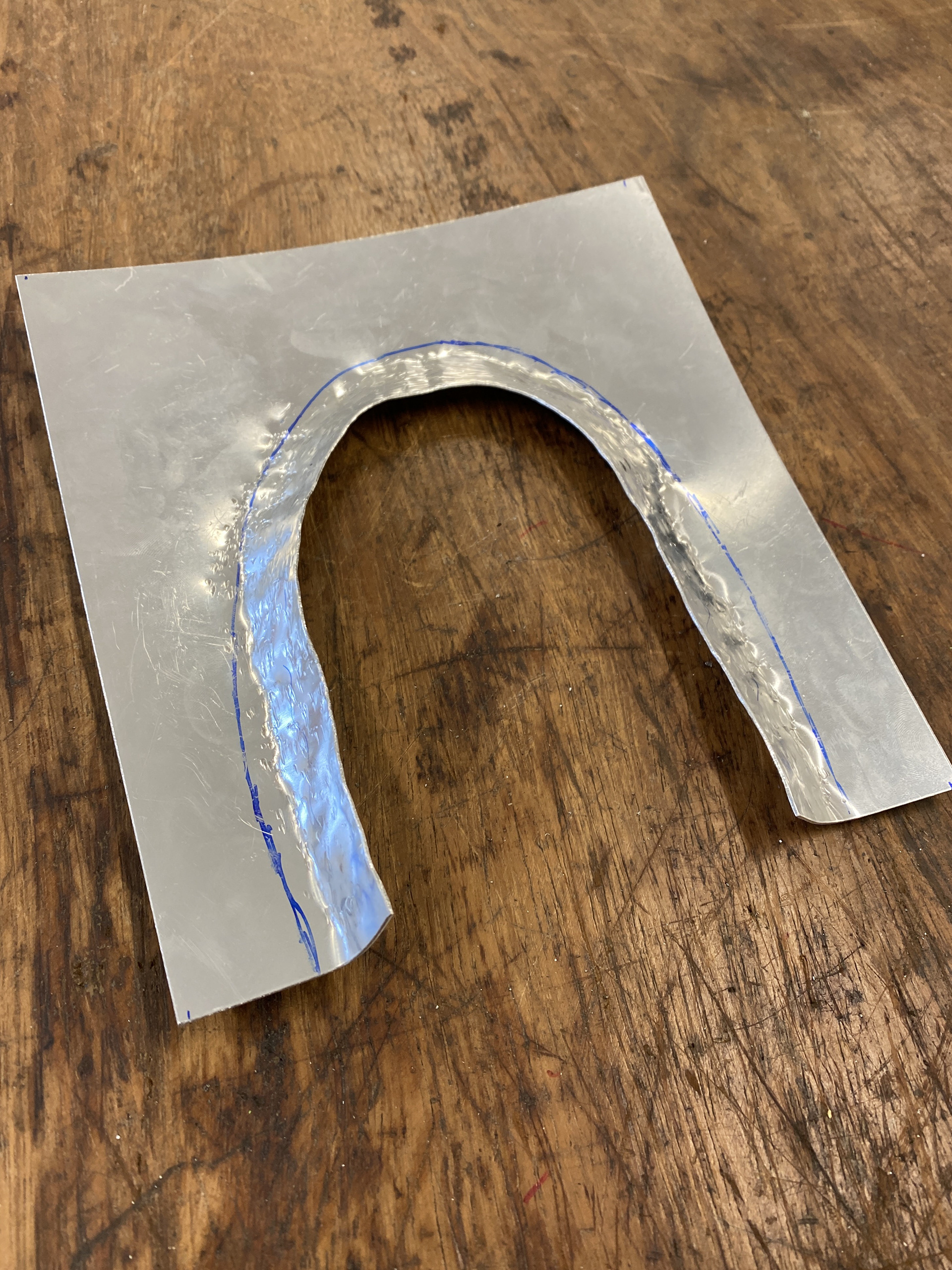
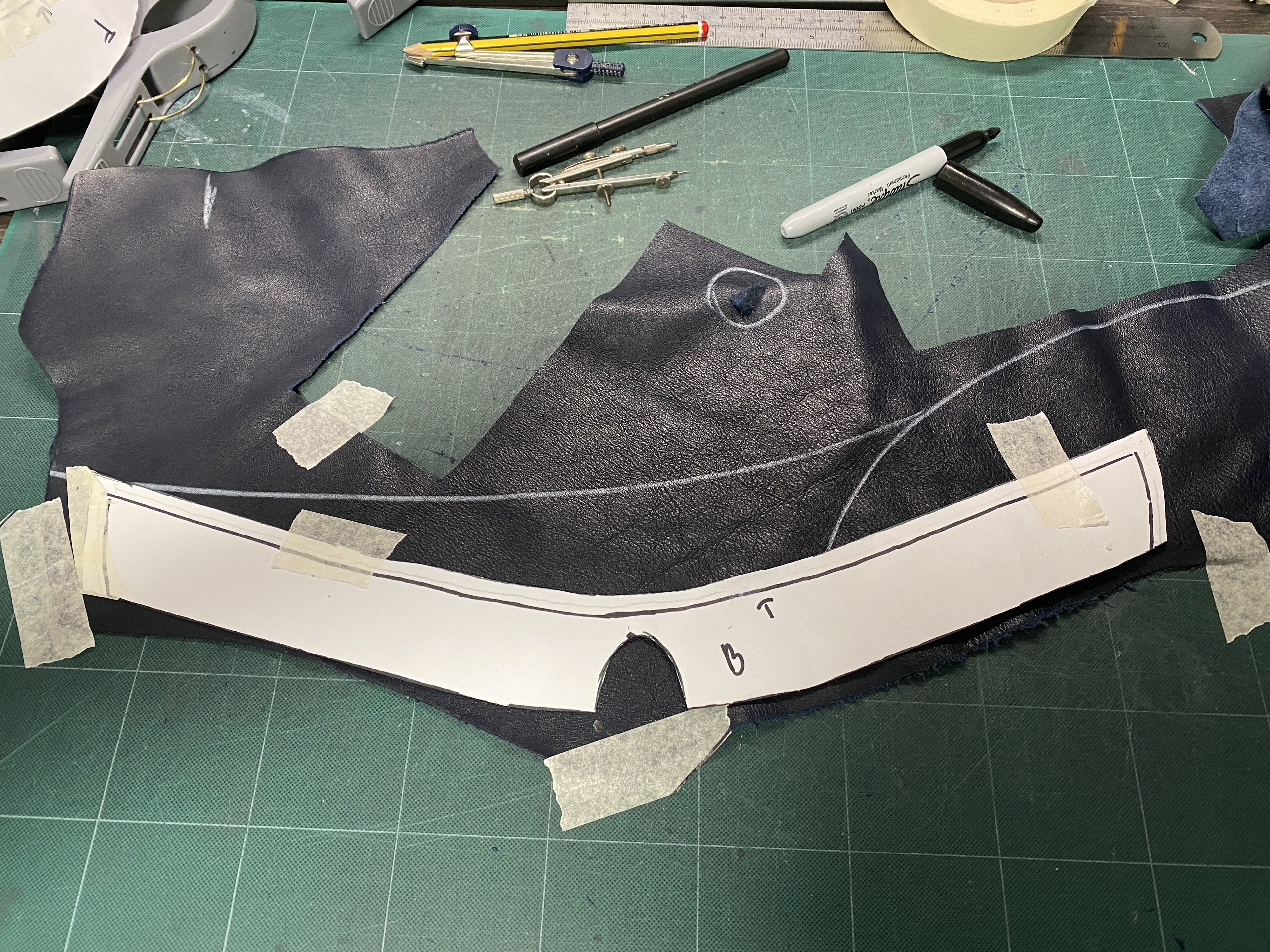
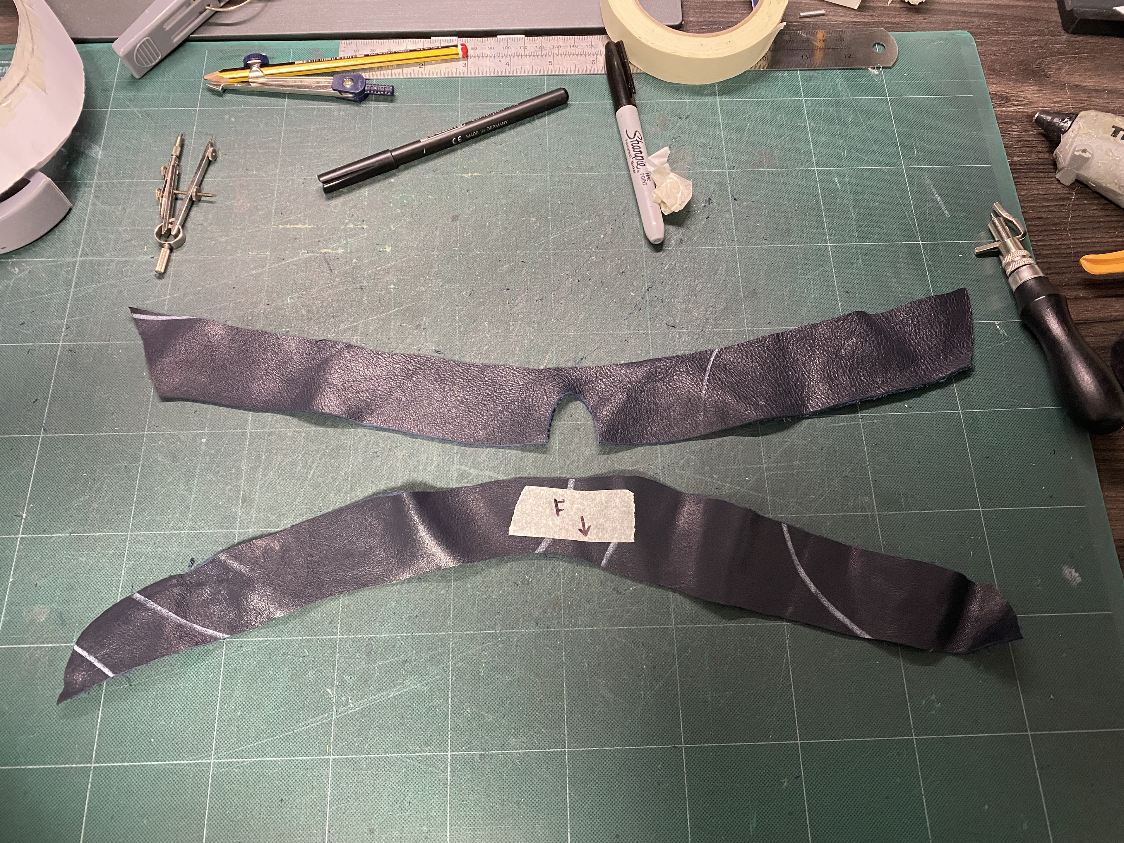
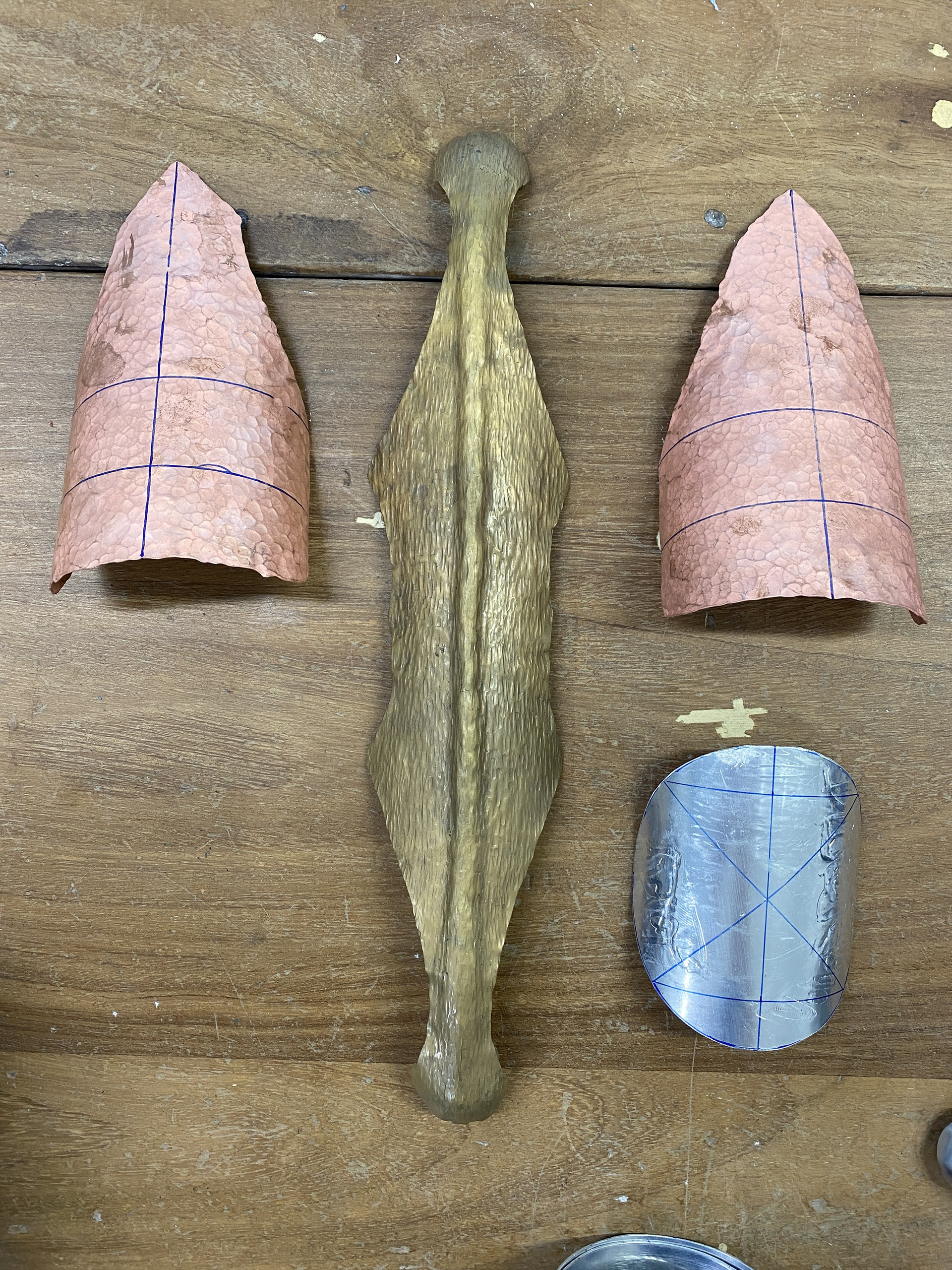
Bringing together the textured back plate, rolled and stamped text and riveting. I found that drilling the rivets once bent and lined up, gave the cleanest and most accurate connection. However, I annealed the copper base plate to form it and when drilling into it, the pillar drill bent it out of shape, making it harder to realign for the riveting. In the future I think that hammering the piece against the stake using a rubber mallet would stiffen up the piece so that it won’t deform. One challenge was finding the stakes which fit under curved surfaces to create the rivets whilst not deforming the piece. I think that the backing piece has too many harsh edges and I want to explore using more fluid and organic shapes mirroring the body.
0.5mm 0.7mm 0.9mm 1.2mm
0.5mm 0.7mm 0.9mm 1.2mm 1.6mm
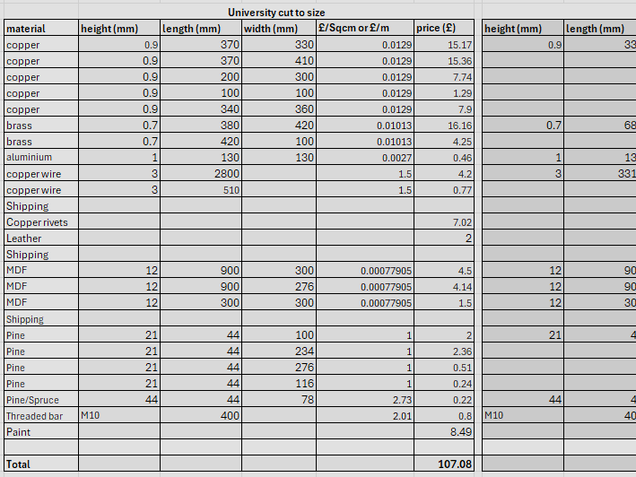
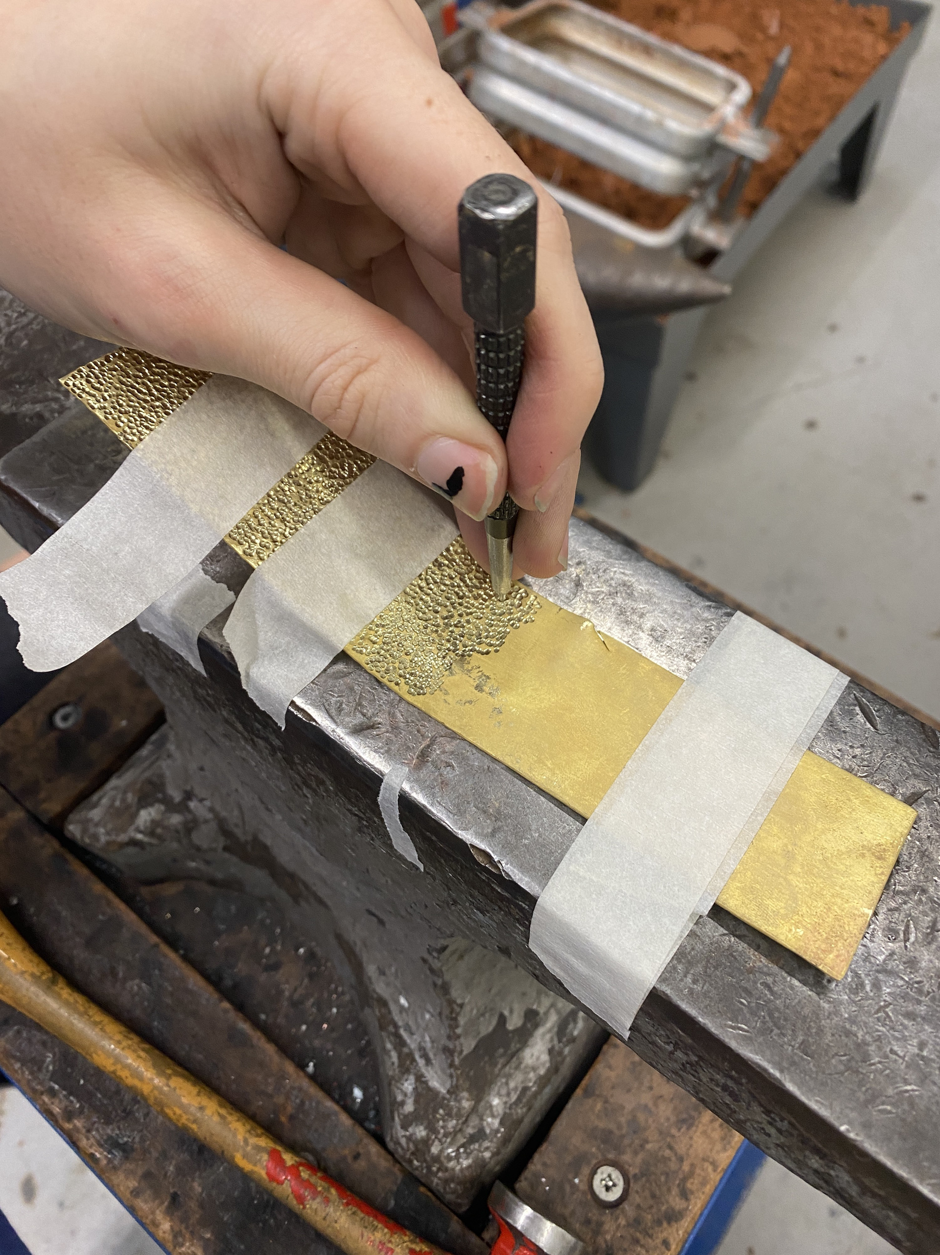
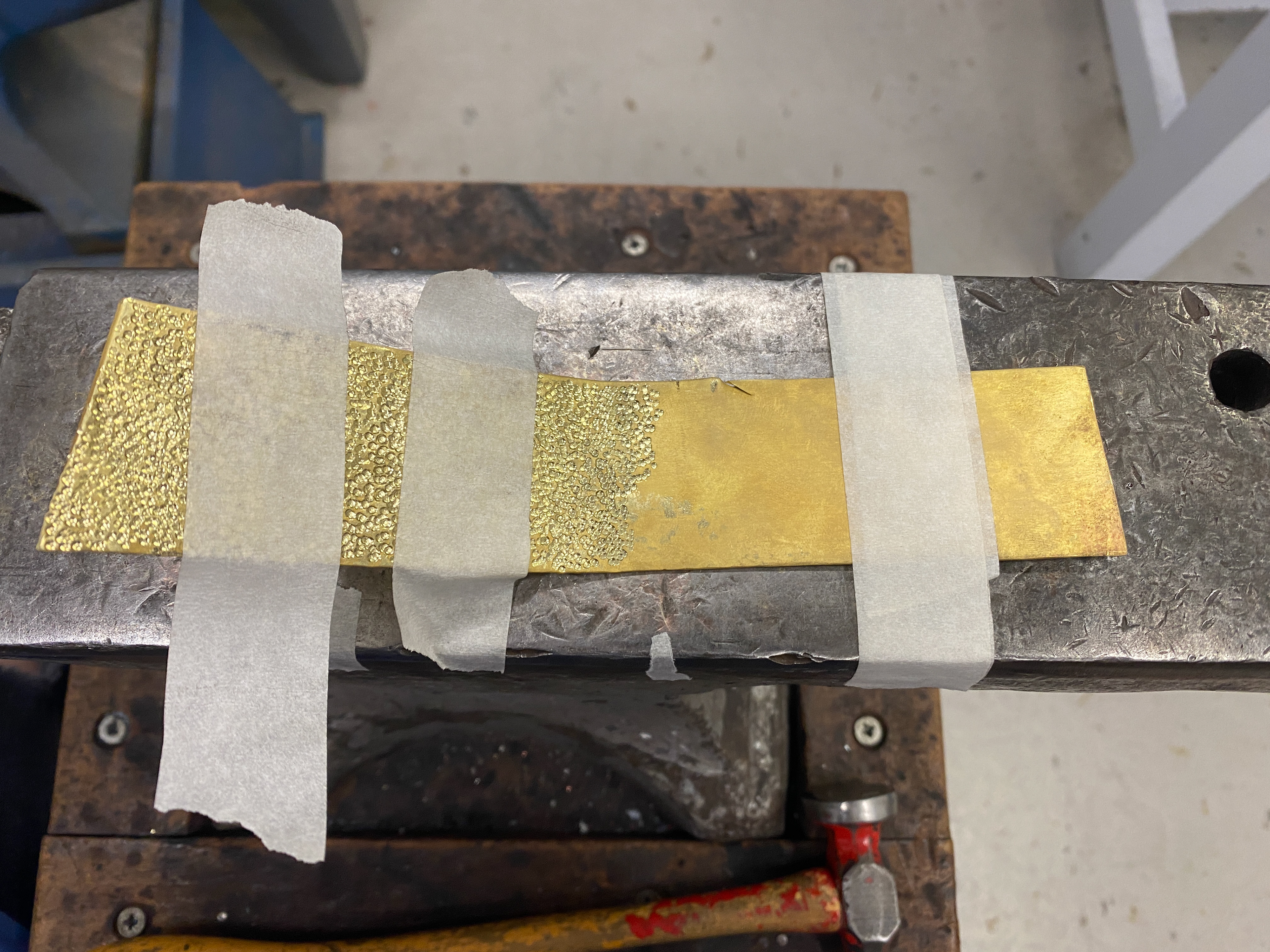
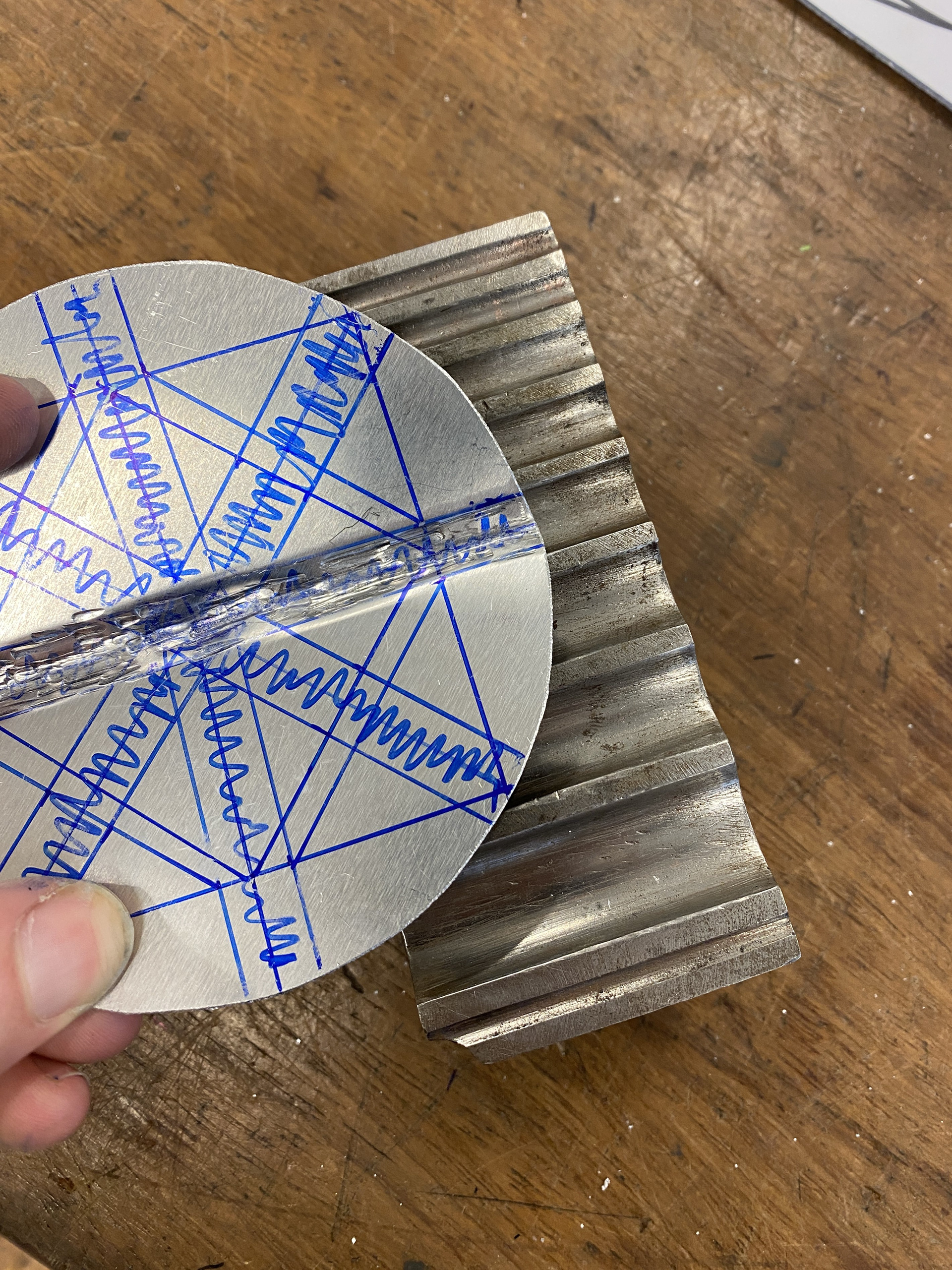
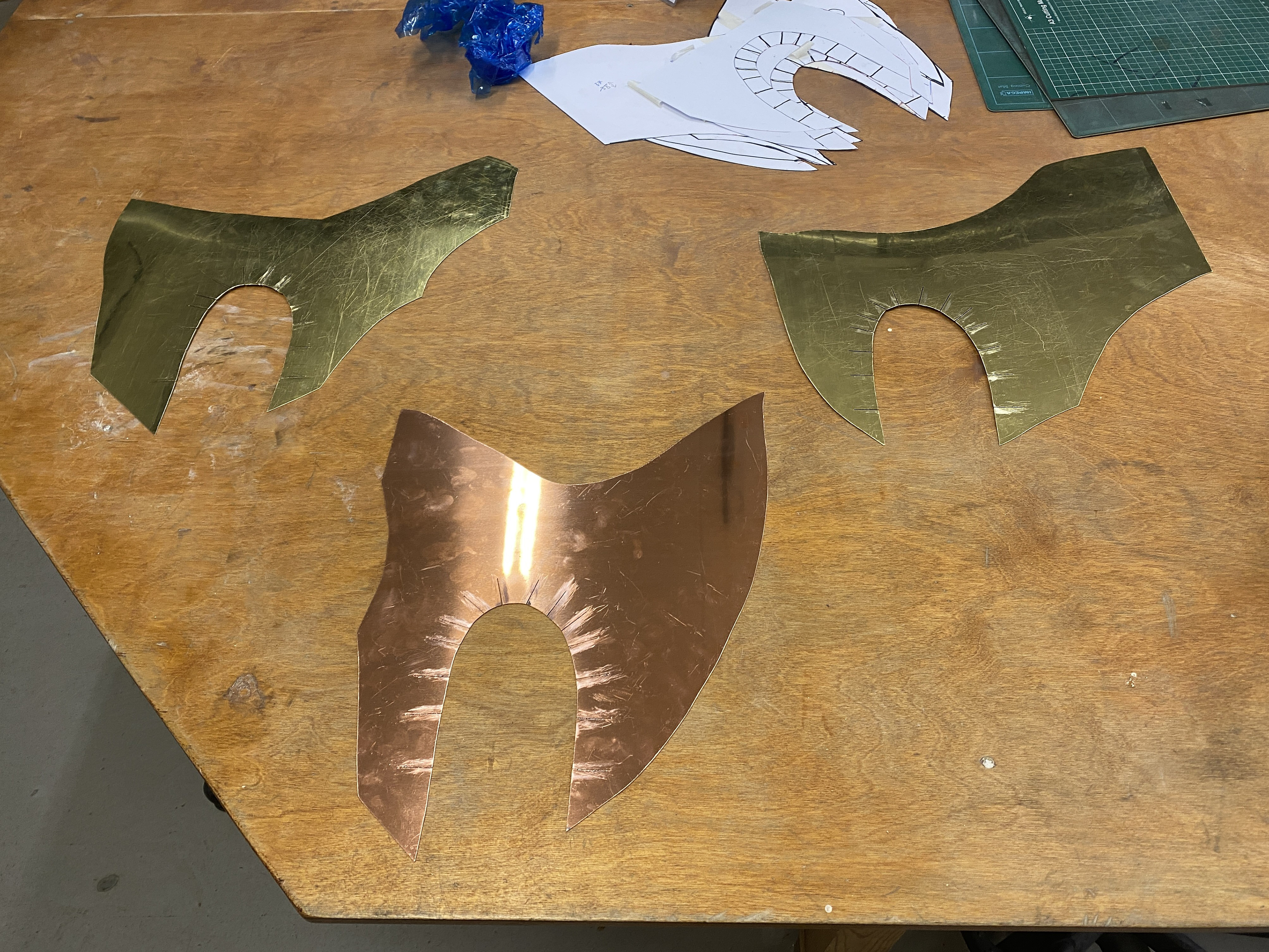
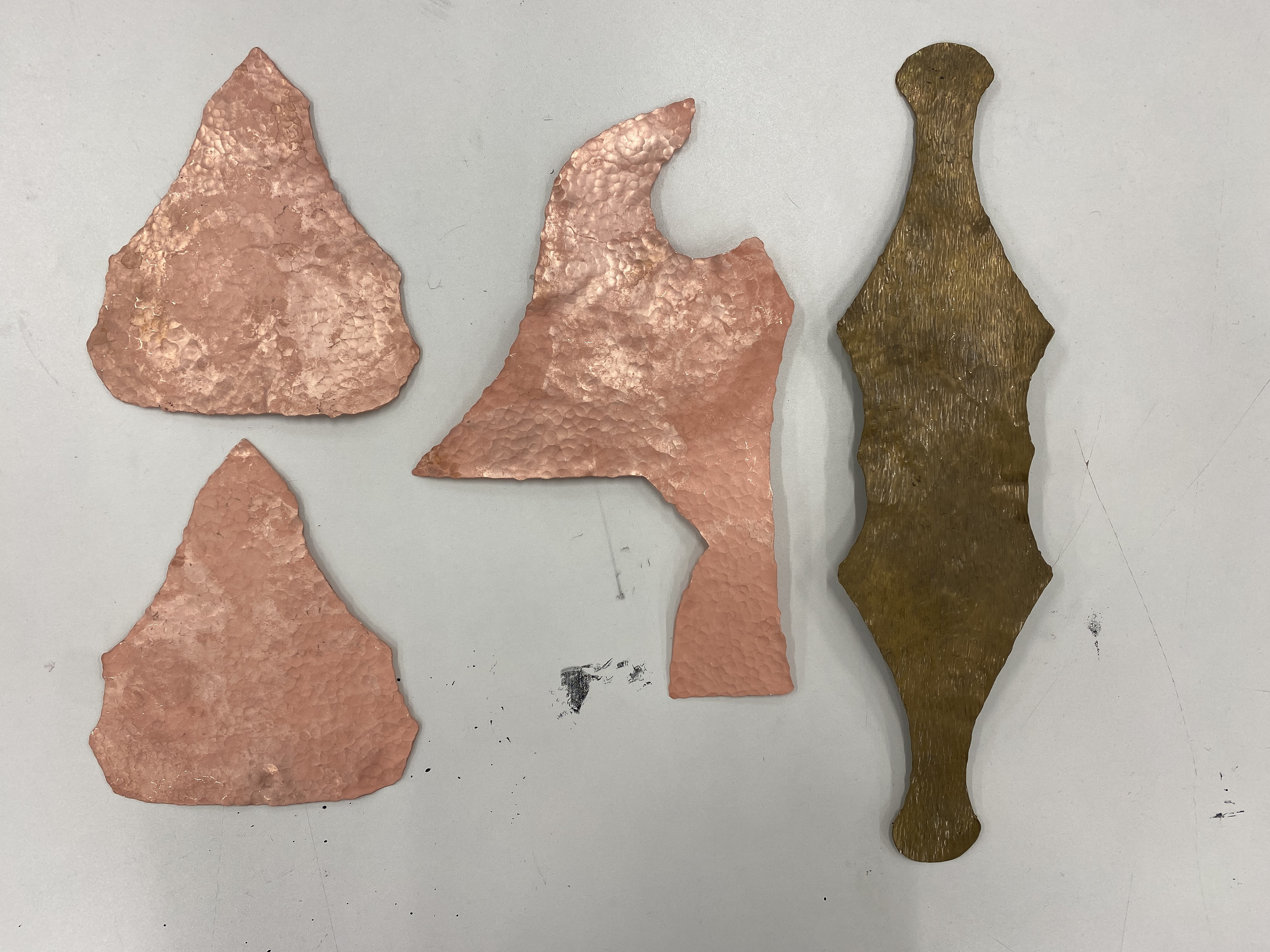
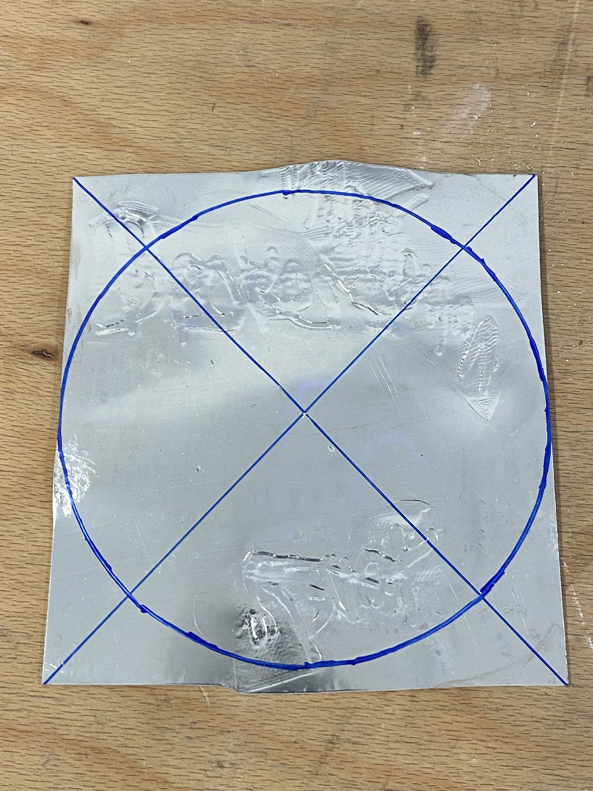
During previous tests I have experimented with a variety of different textures but not directly compared these marks on differing material thicknesses. I used the same ball peen hammer to texture annealed copper and brass. I found that the 0.9mm copper and 0.7mm brass gave the best combination of visible texture whilst being lightweight enough in larger sheets and forms. Whilst the 1.2mm copper and brass has a higher clarity of mark due to the increased material displaced during hammering. I would only use the 1.2mm for smaller sections due to its weight on the body.
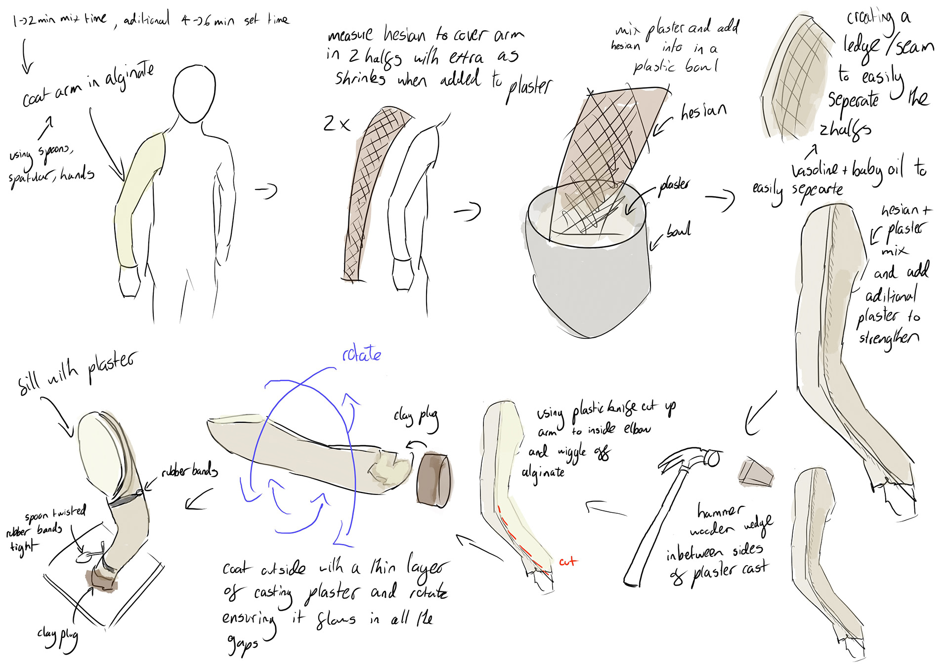
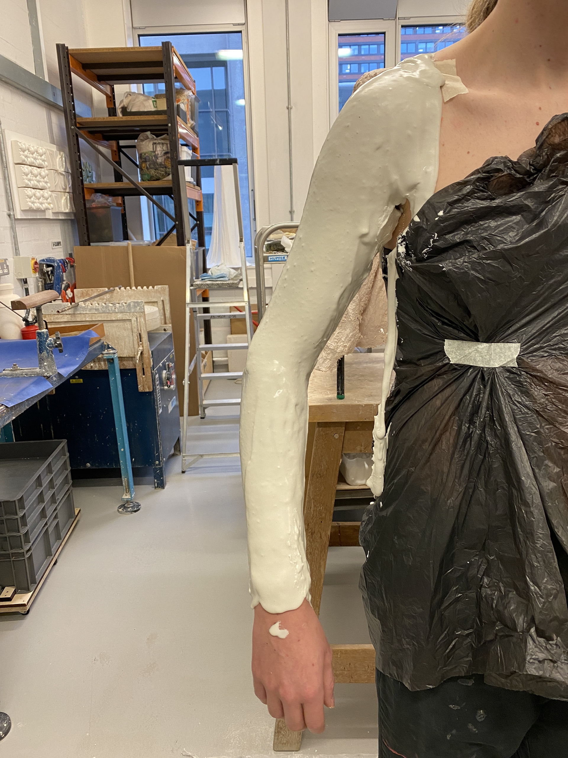
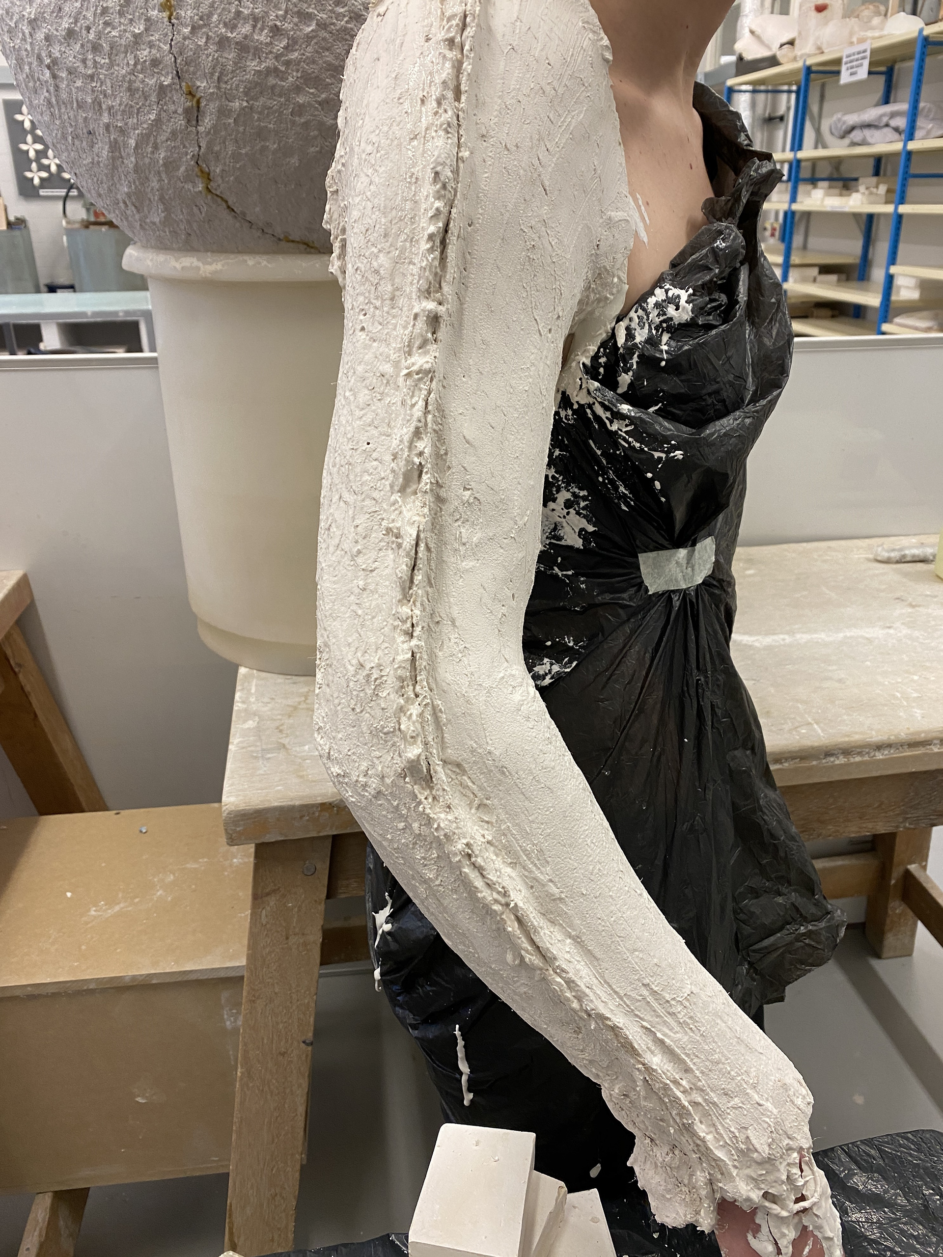
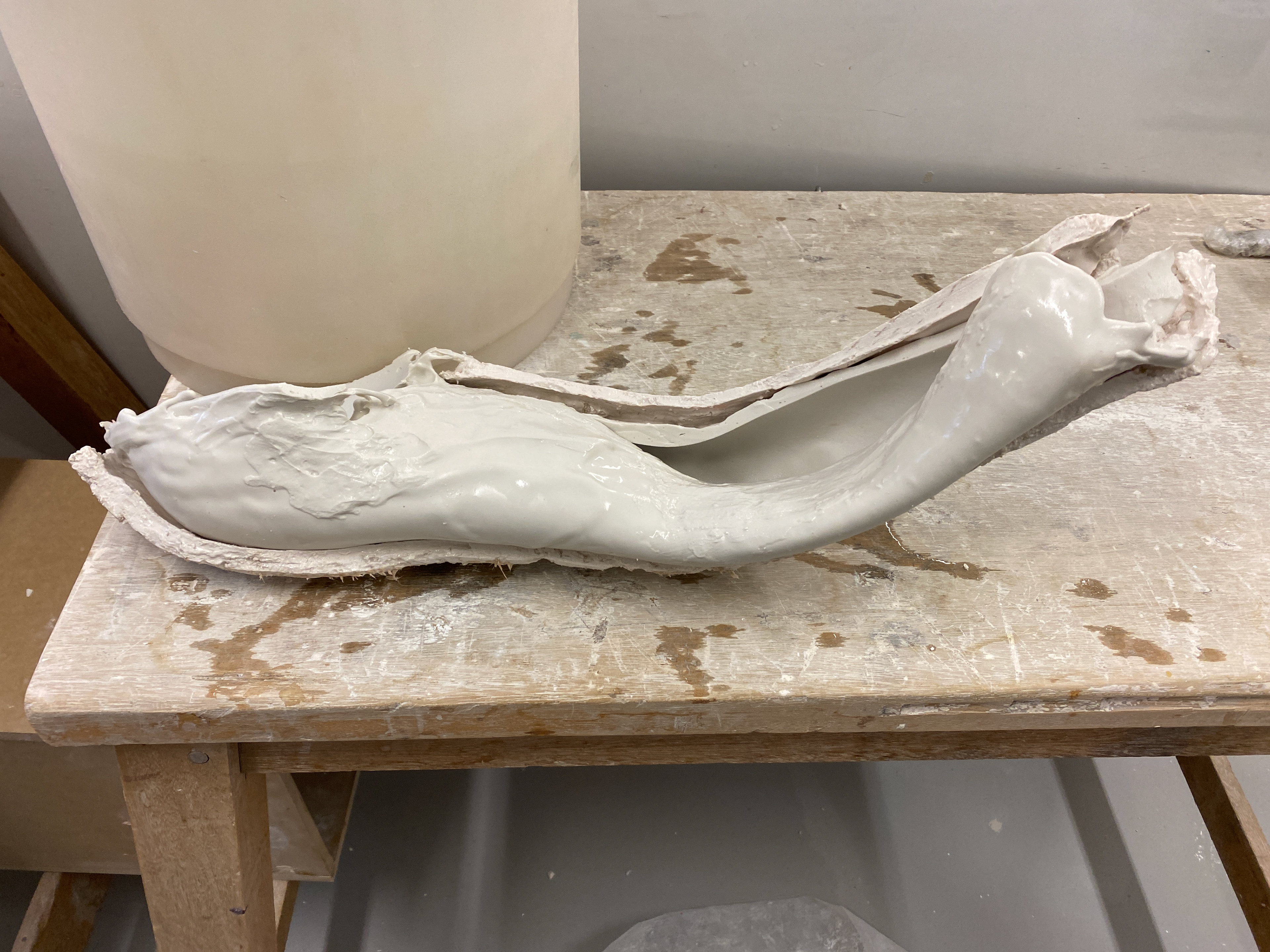
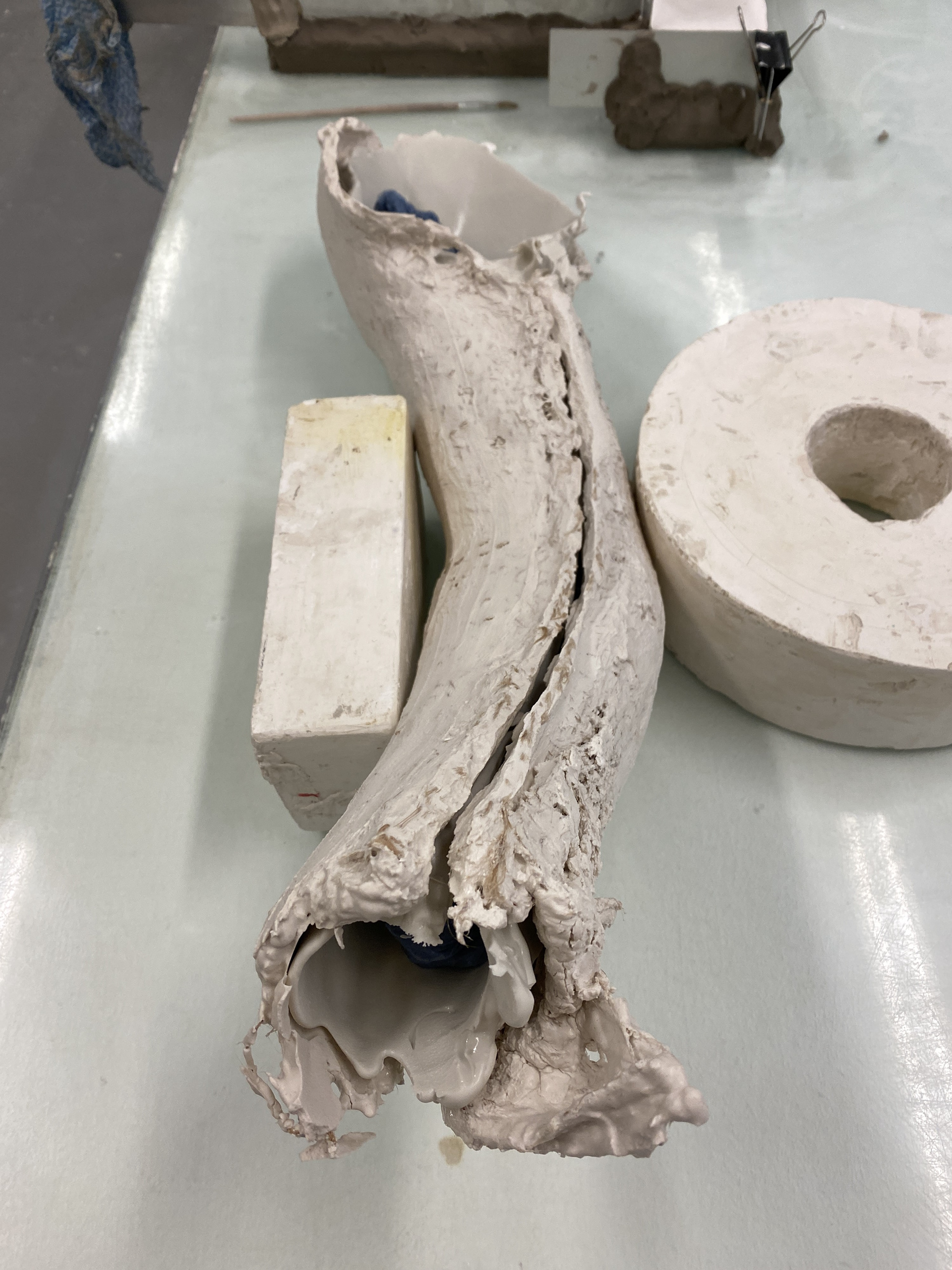
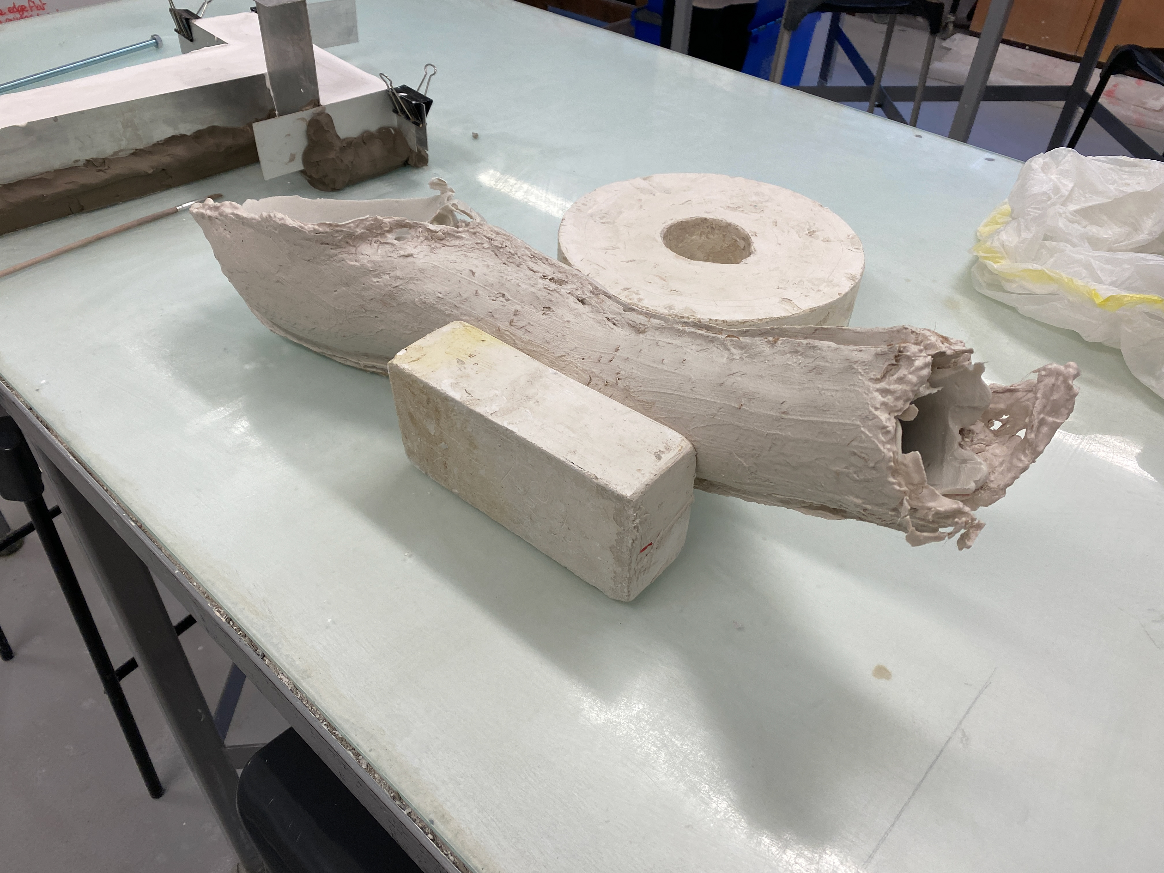
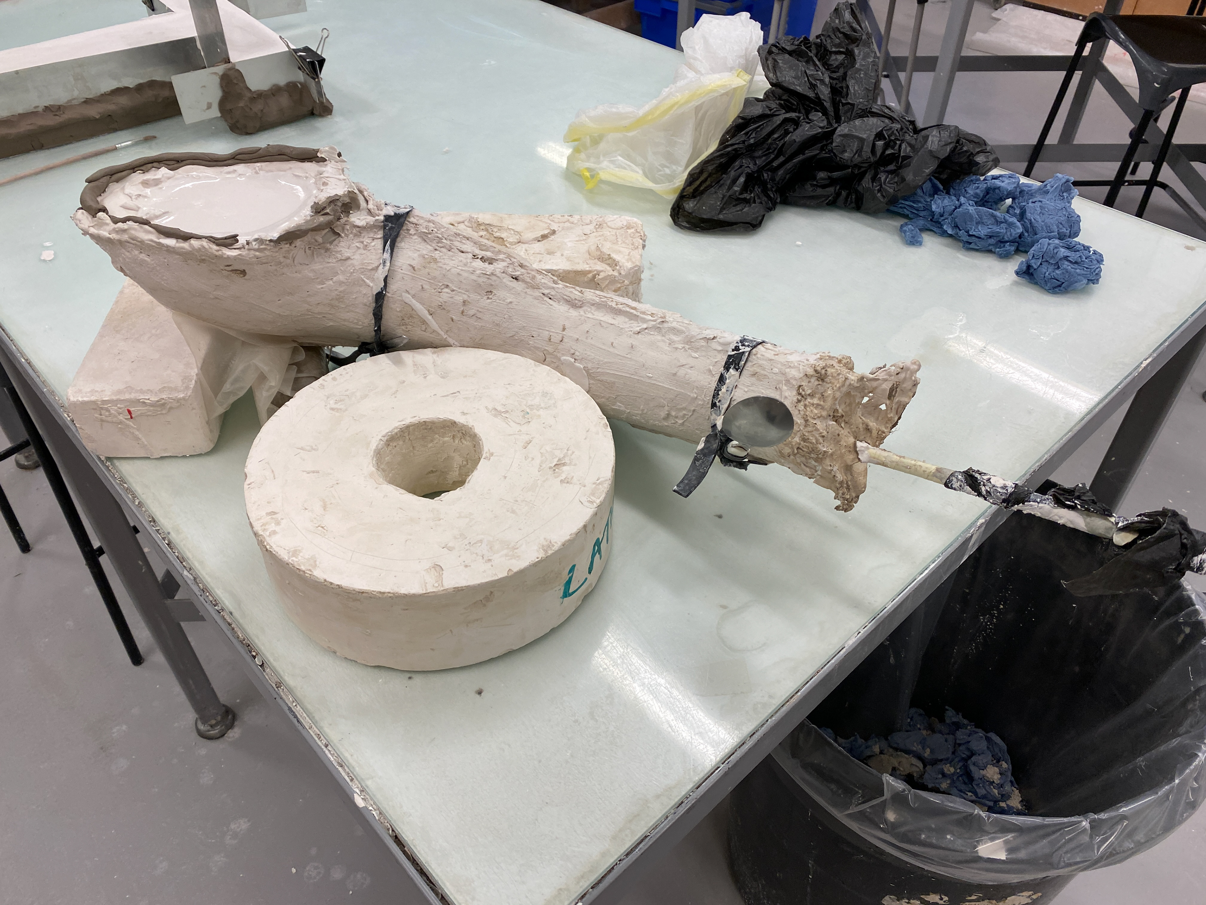
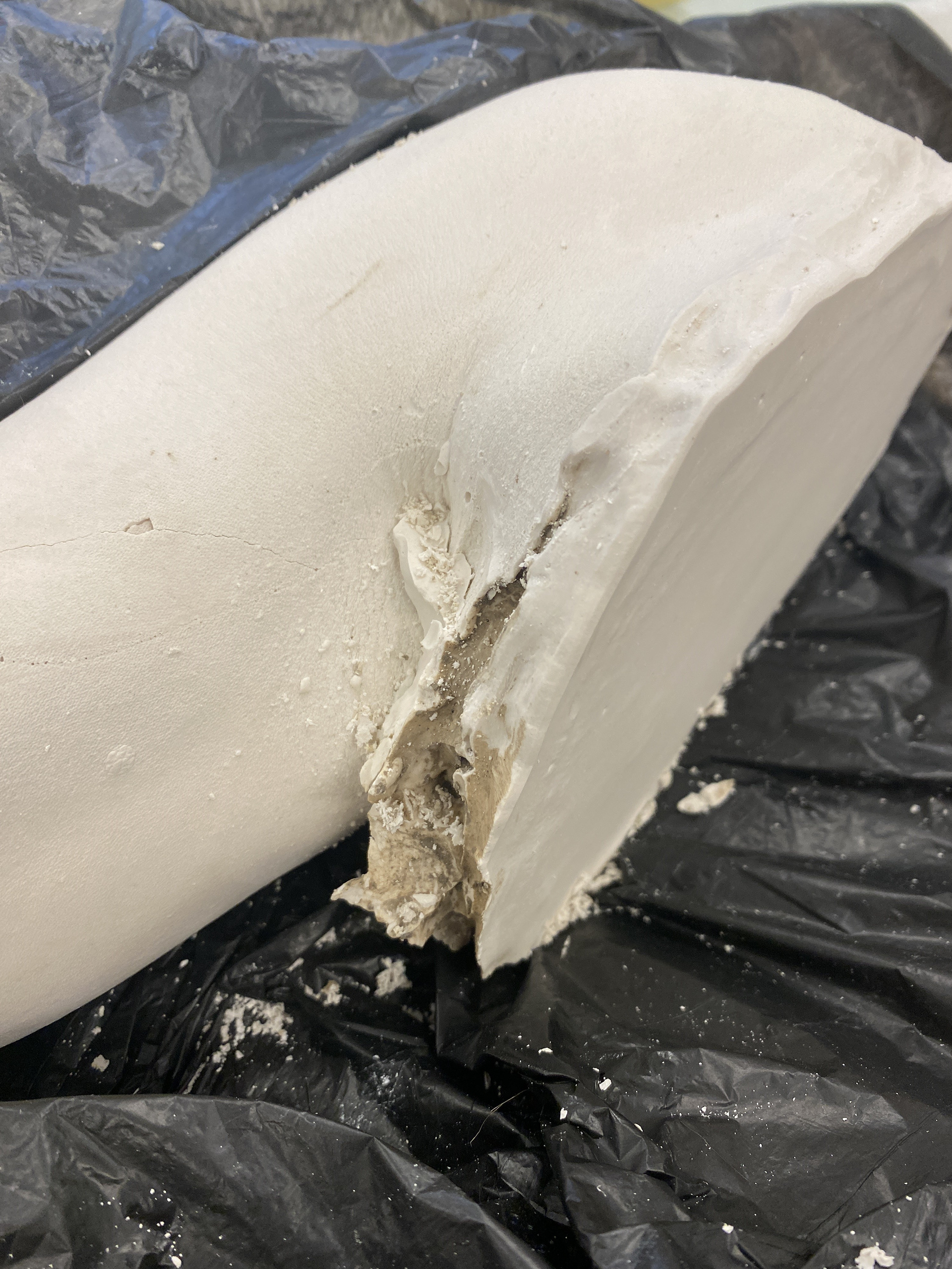
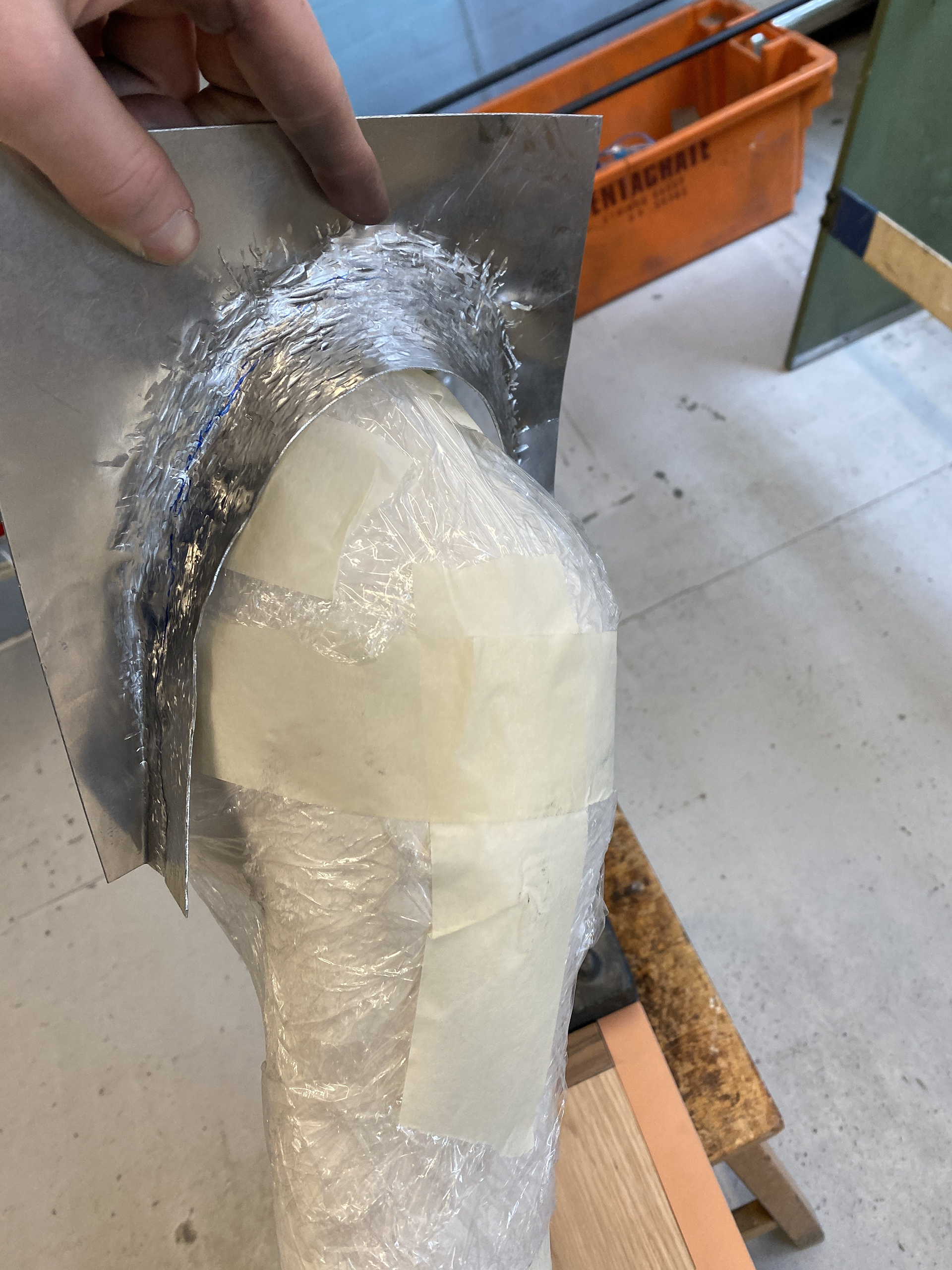
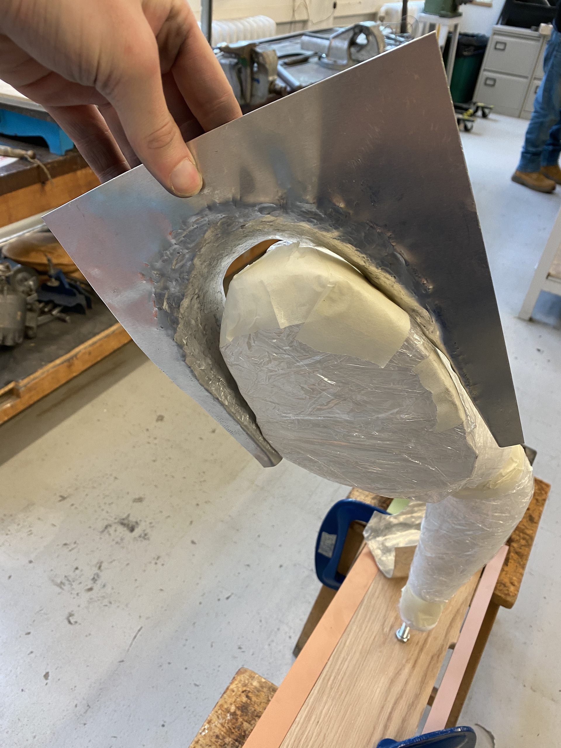
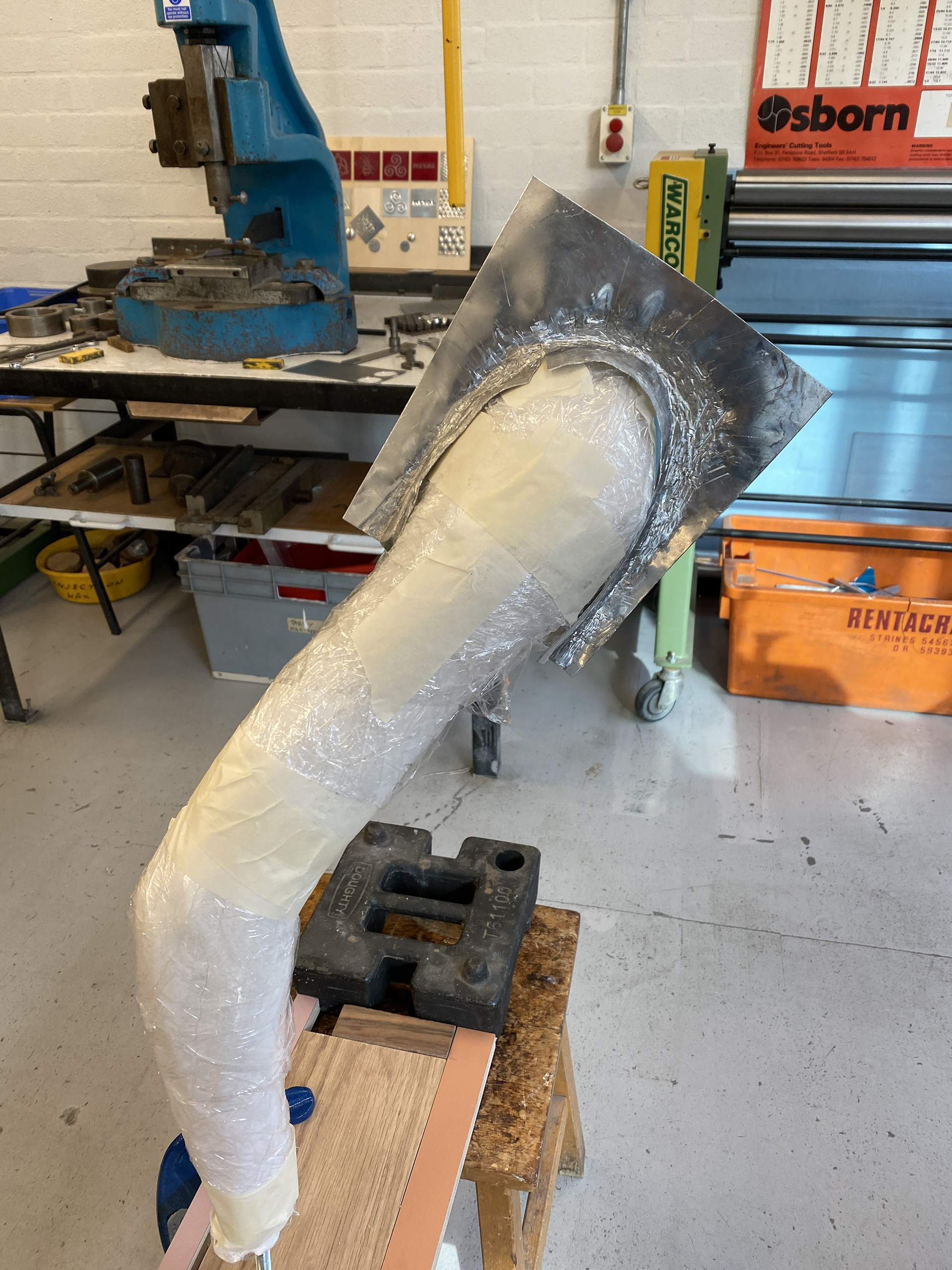
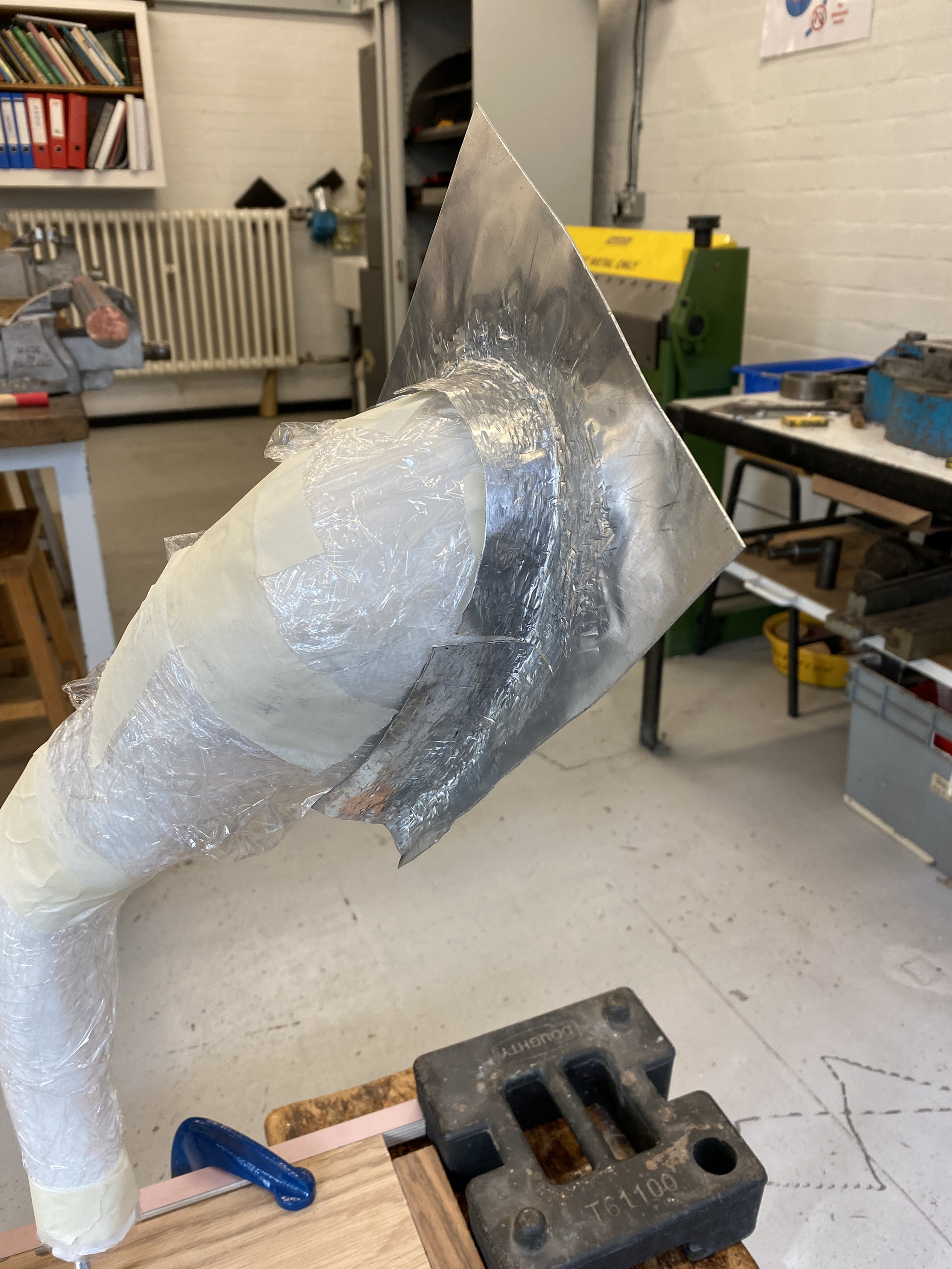
Creating a cast of my shoulder and arm
I have been struggling to create forms that mould over my body both during the design stage and in material testing. Therefore, I decided to create a body cast of my shoulder and arm so that I can work directly onto it using paper and wire to soft model as well as place more refined metal pieces over and adjust accordingly. Also, this cast will serve as a platform to display my final work ready for exhibition. Presenting it on a cast of myself will keep the connection between the individual and the work that sits on top.
Documenting the process through photography

Experimenting with blacksmithing to create cage designs inspired by sword hilts
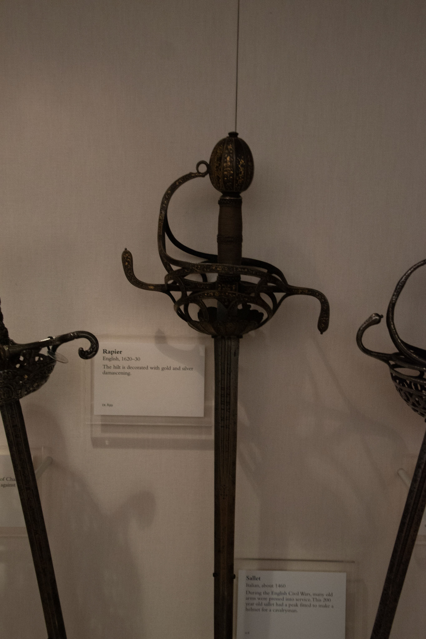
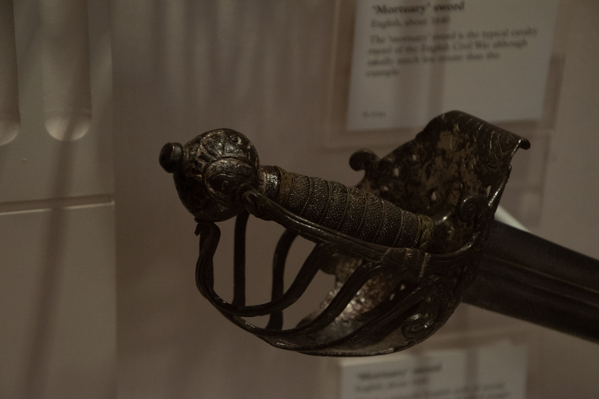
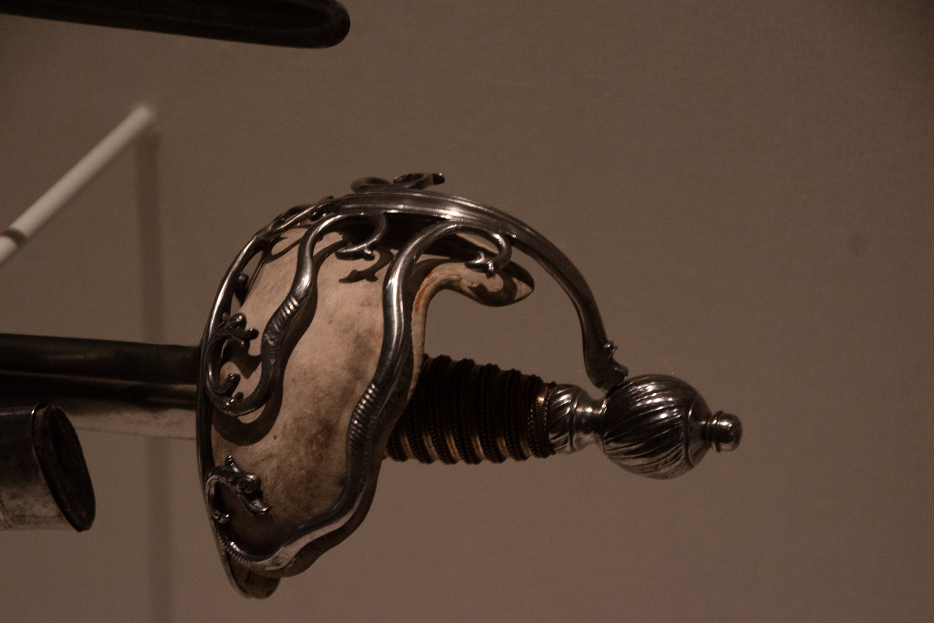
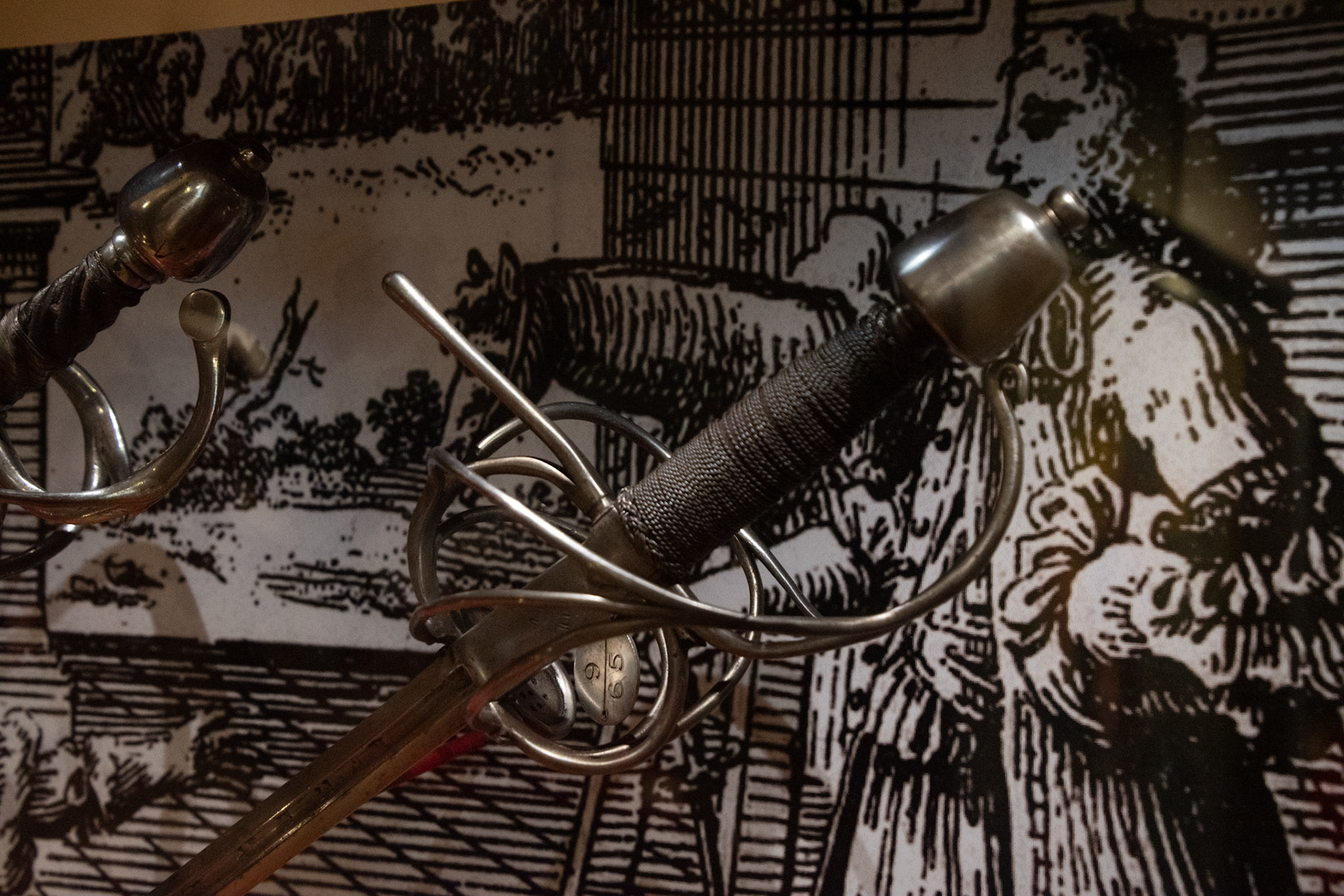
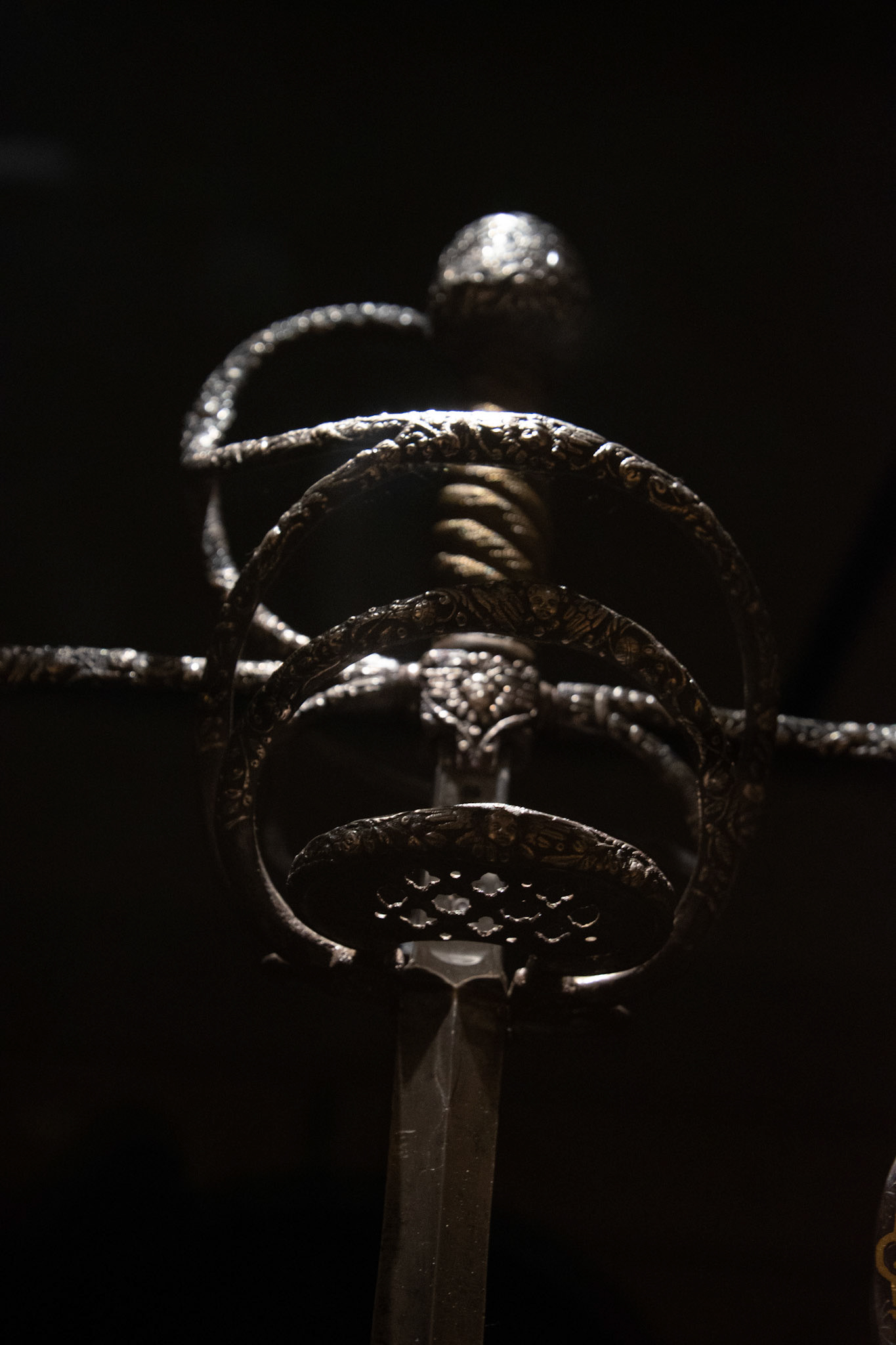
Sword hilt inspiration from Leeds Armoury trip
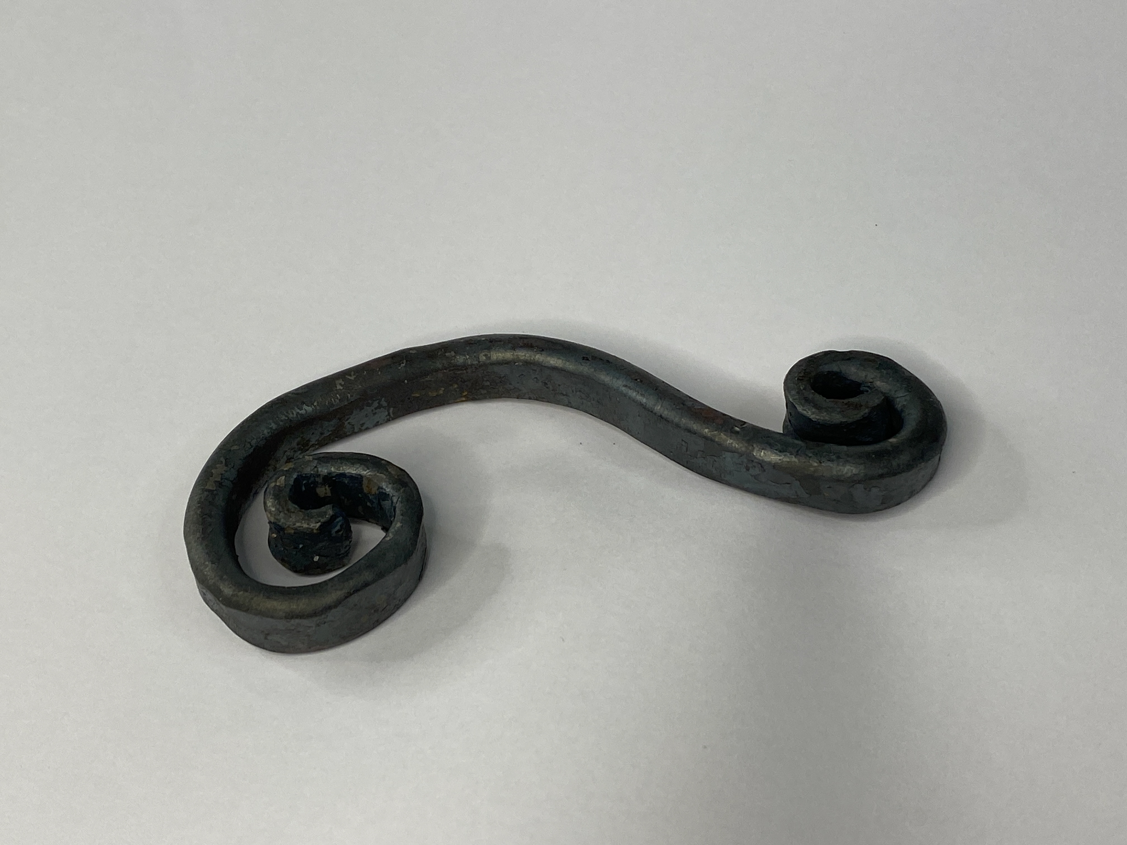
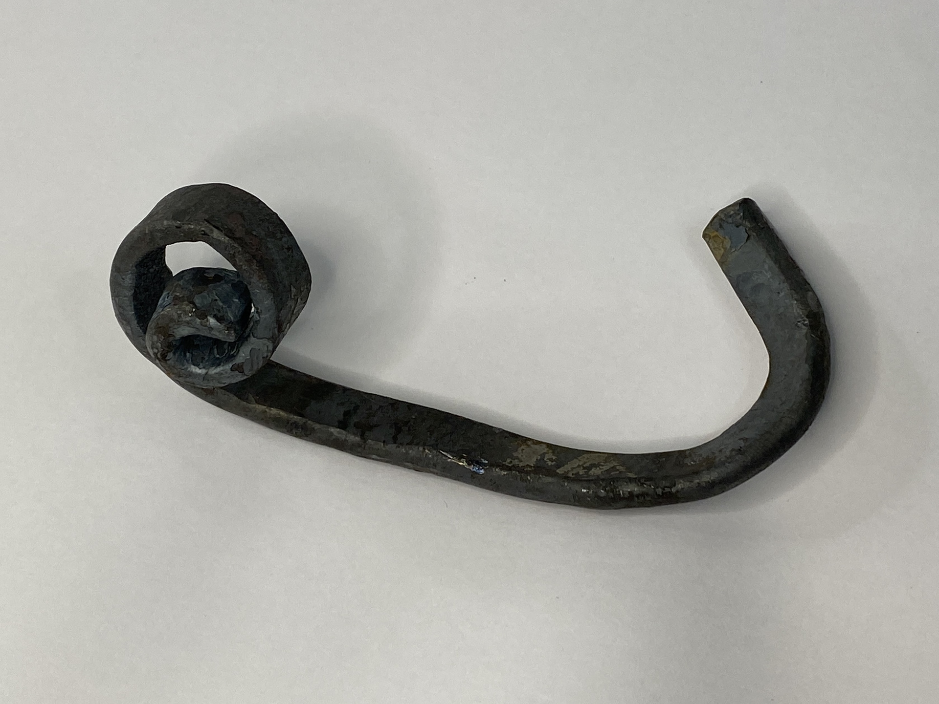
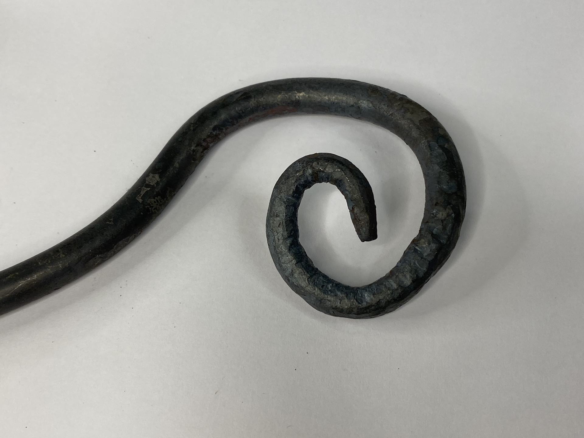
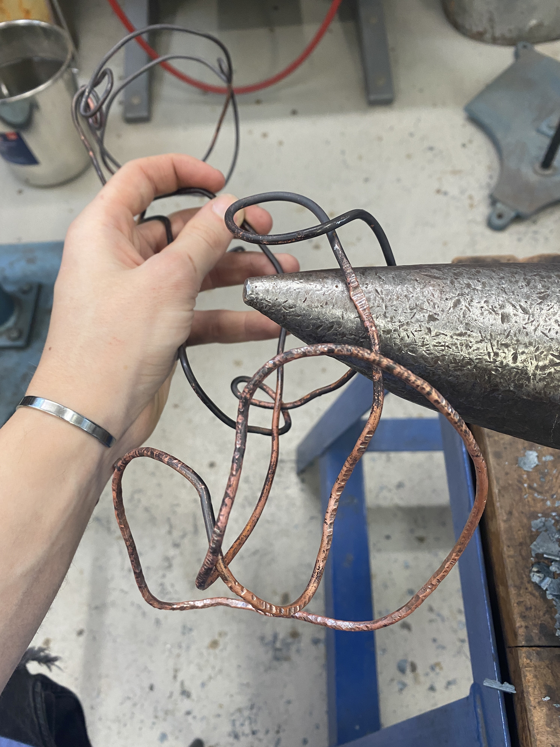
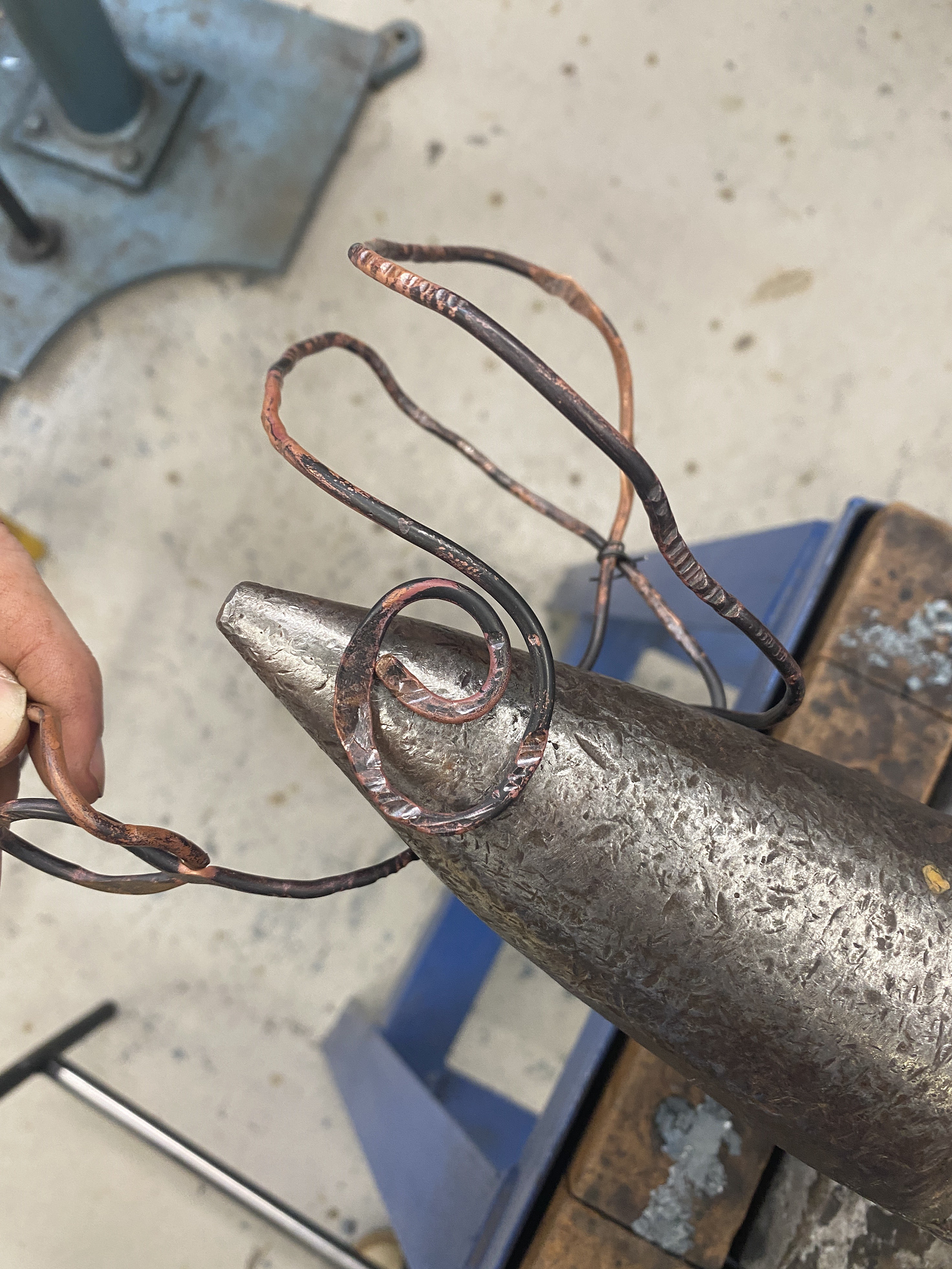
Practicing different ways to create scrolls and curves using the horn of the anvil as well as tongs and pliers. Also, drawing down and flattening out 10mm round bar to create tapers and flat sections to be twisted and manipulated.
Manipulating 5mm steel round bar over a form looking at encapsulation and trapping the object. Working with thin material allowed me to bend and easily manipulate the shape but when placed into the forge it tended to spring back and deform due to the temperature change. I would also like to introduce some more embellishment and connecting pieces to my next designs.
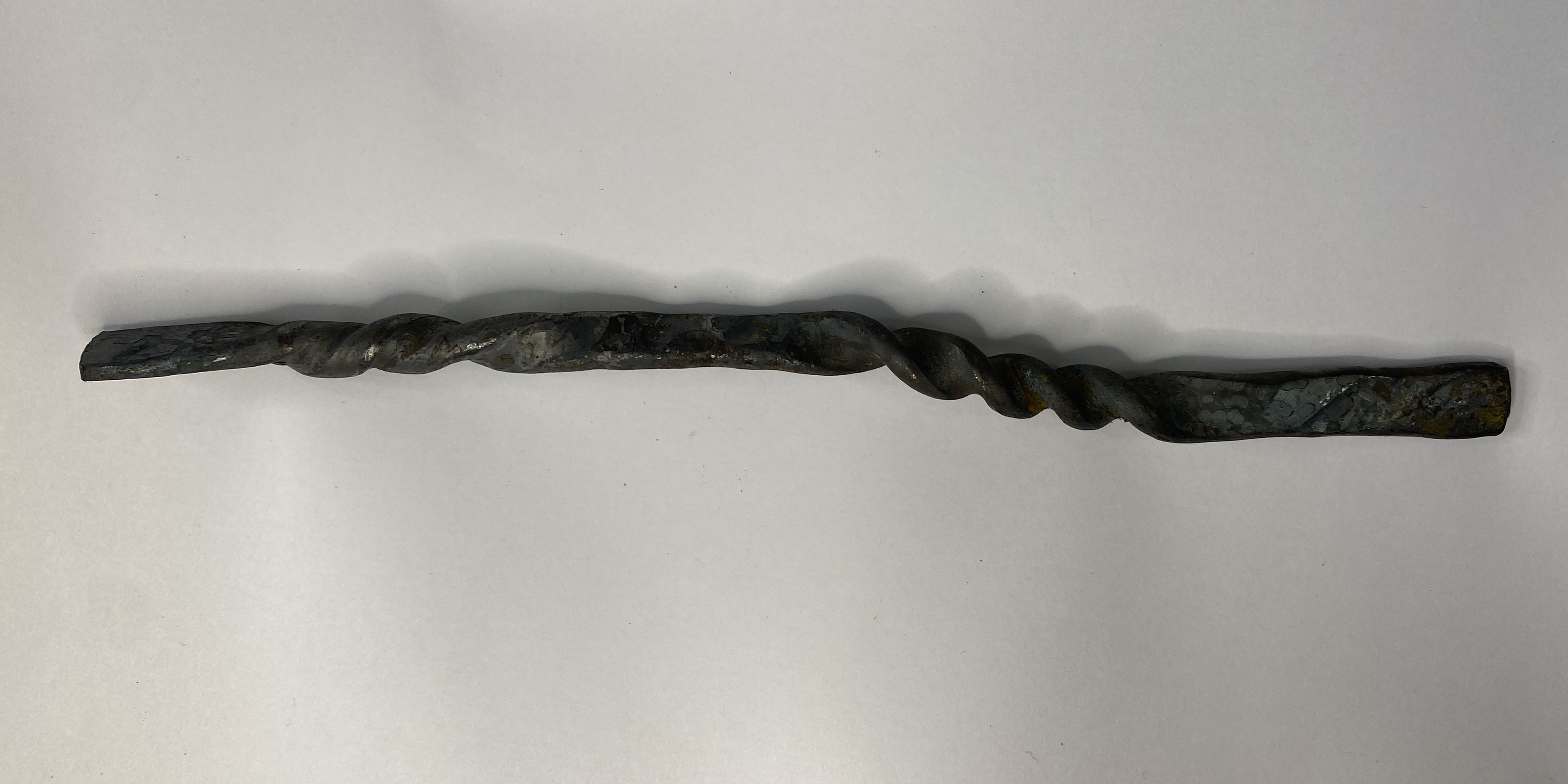
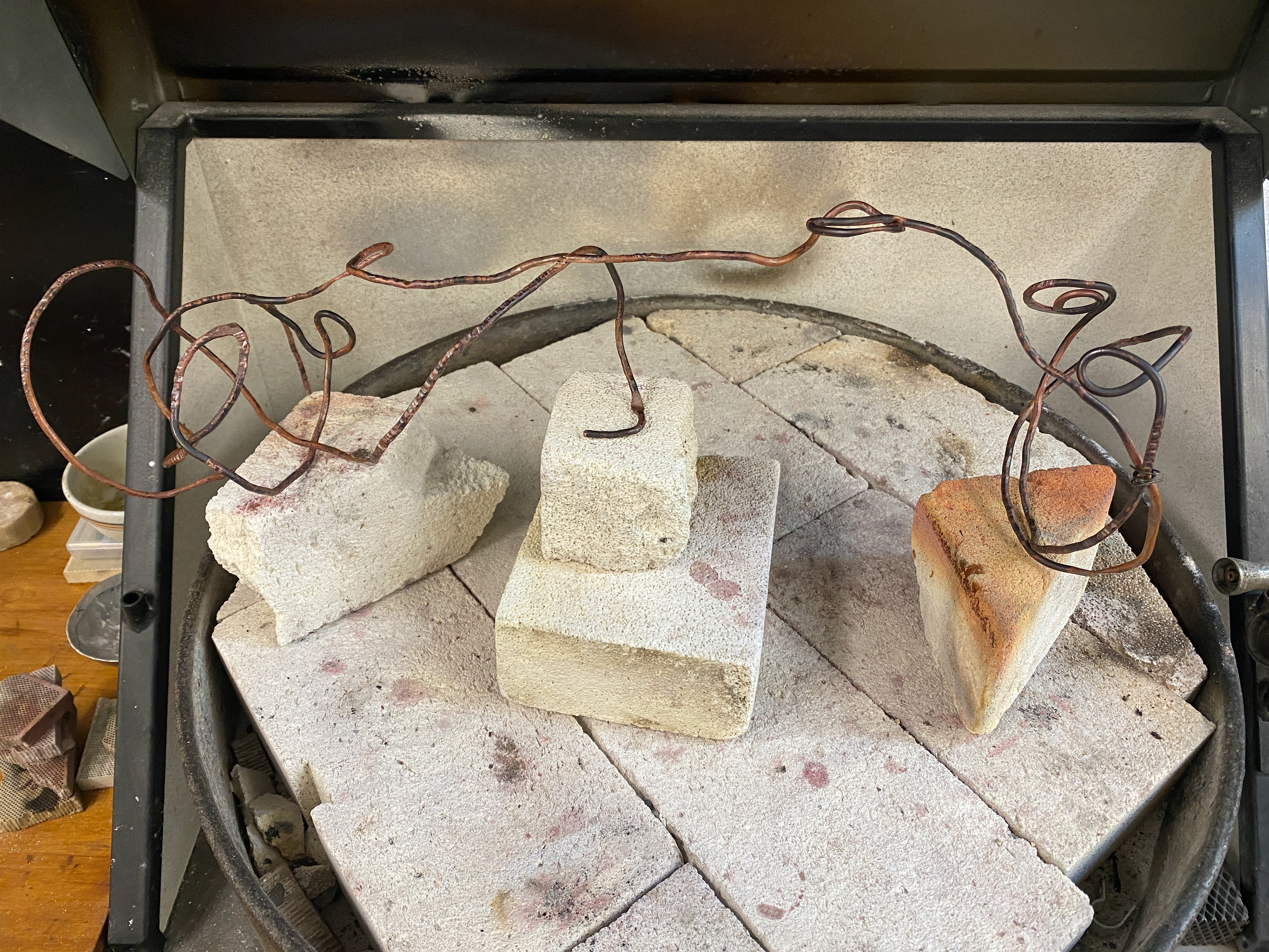
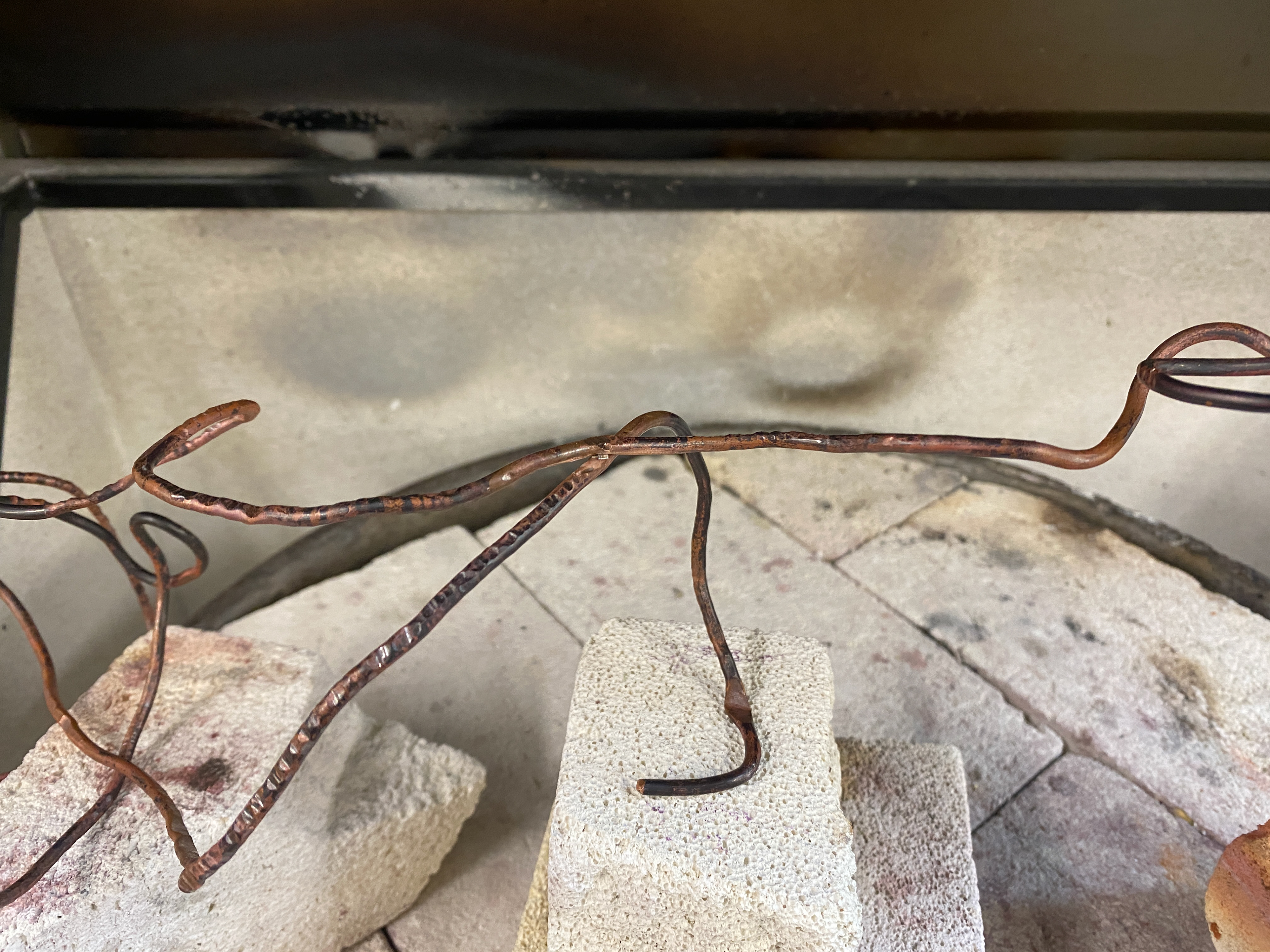
Reflecting further on my pervious piece, I didn't like how refined, and factory finished the steel rods look. Therefore, I used the wedge side of the riveting forging hammer to draw down an 800mm long 10mm round bar to create a textured flattened bar. The main challenge of this was heating the centre section of the long bar in the forge which I overcame by building up the ceramic chips higher than usual to surround it.
With the steel bar in my desired shape and texture, I then bent it around a form shaping it using: the horn of the anvil, tongs, pliers and directly onto the form. I also used a leg vice to clamp the workpiece in and twist it using the forging tongs which emphasised the rhythmic flow around the form. I think introducing a variety of thickness and tapered elements would heighten the flow and encapsulation.
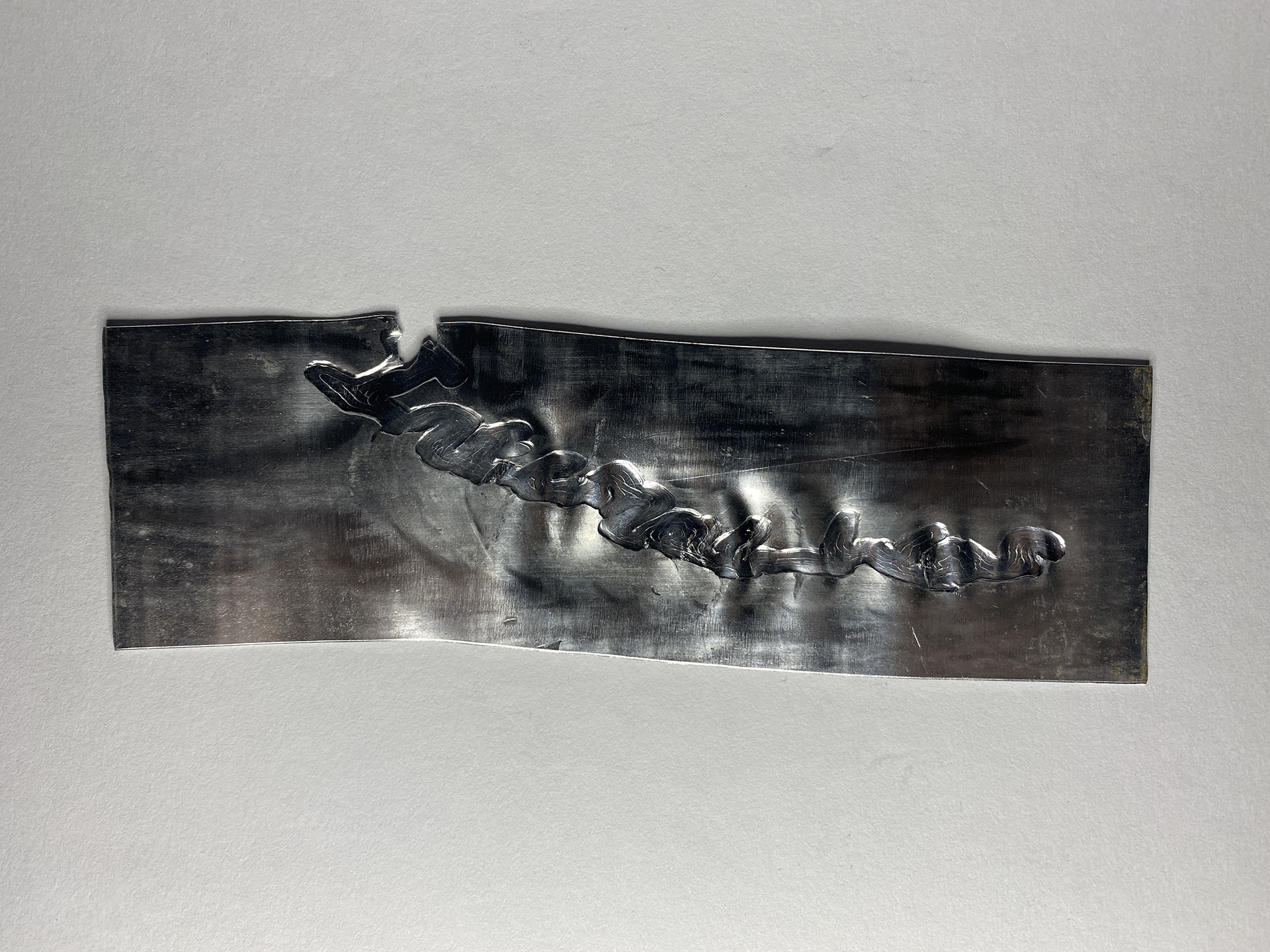
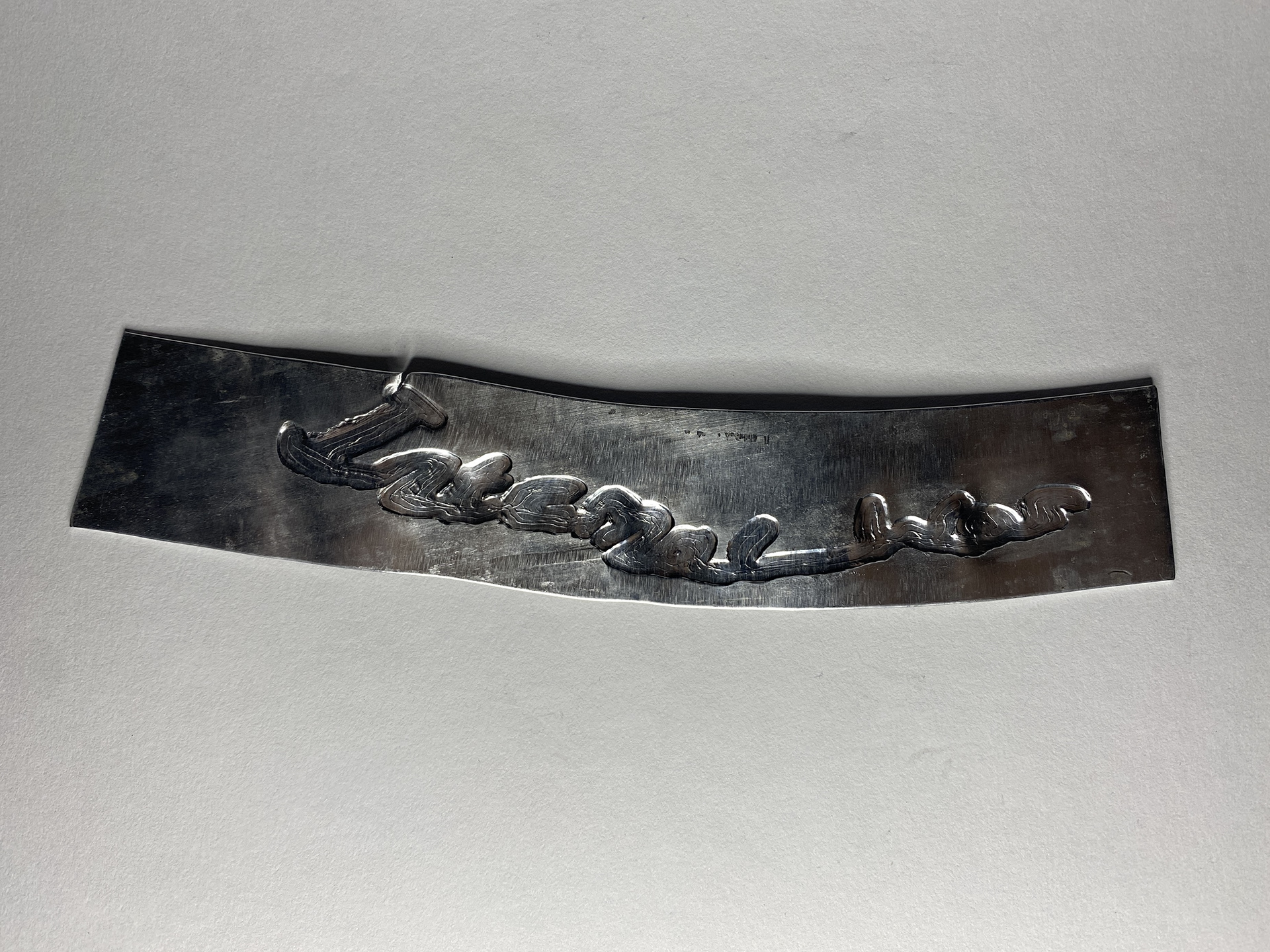
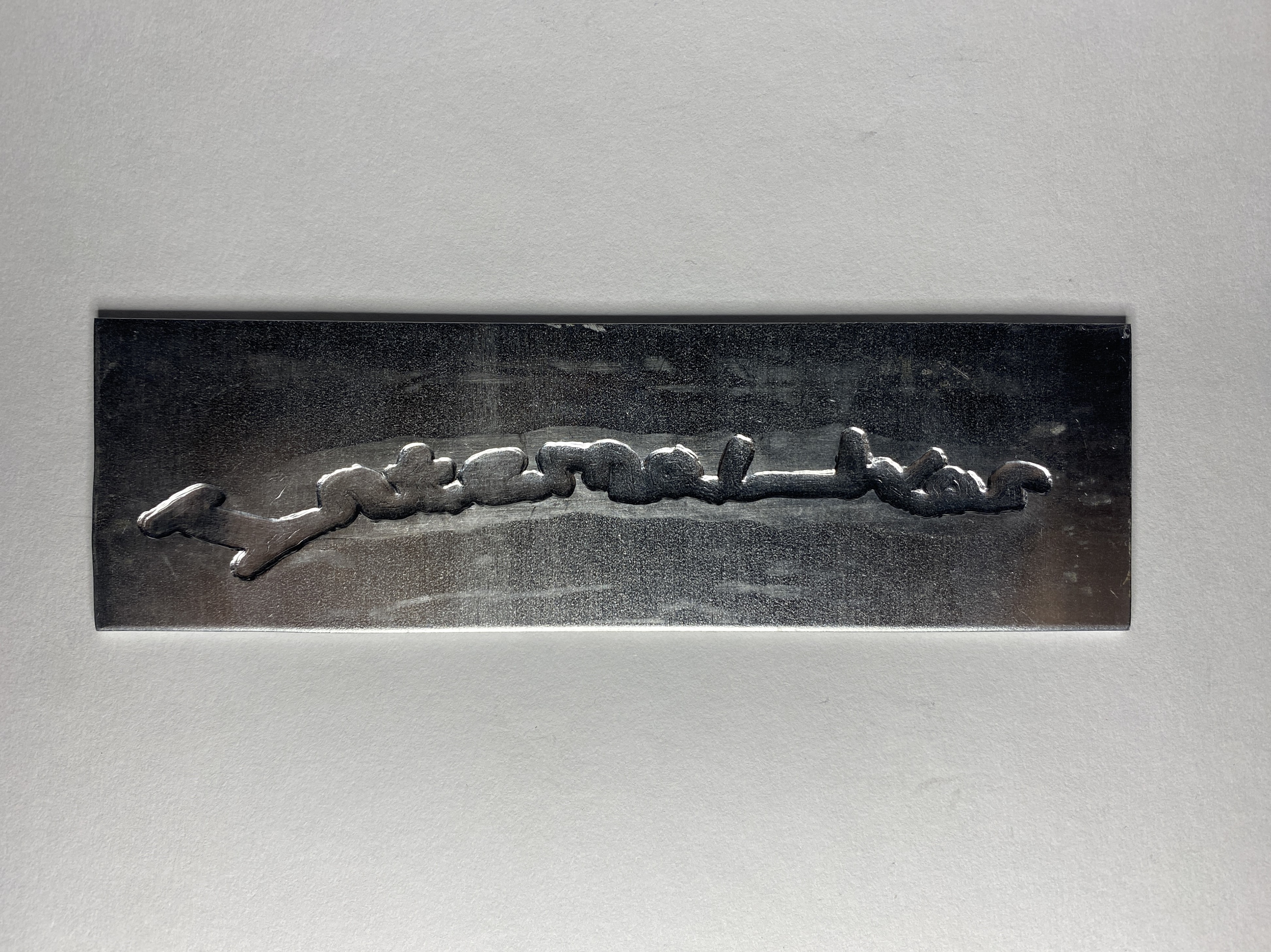
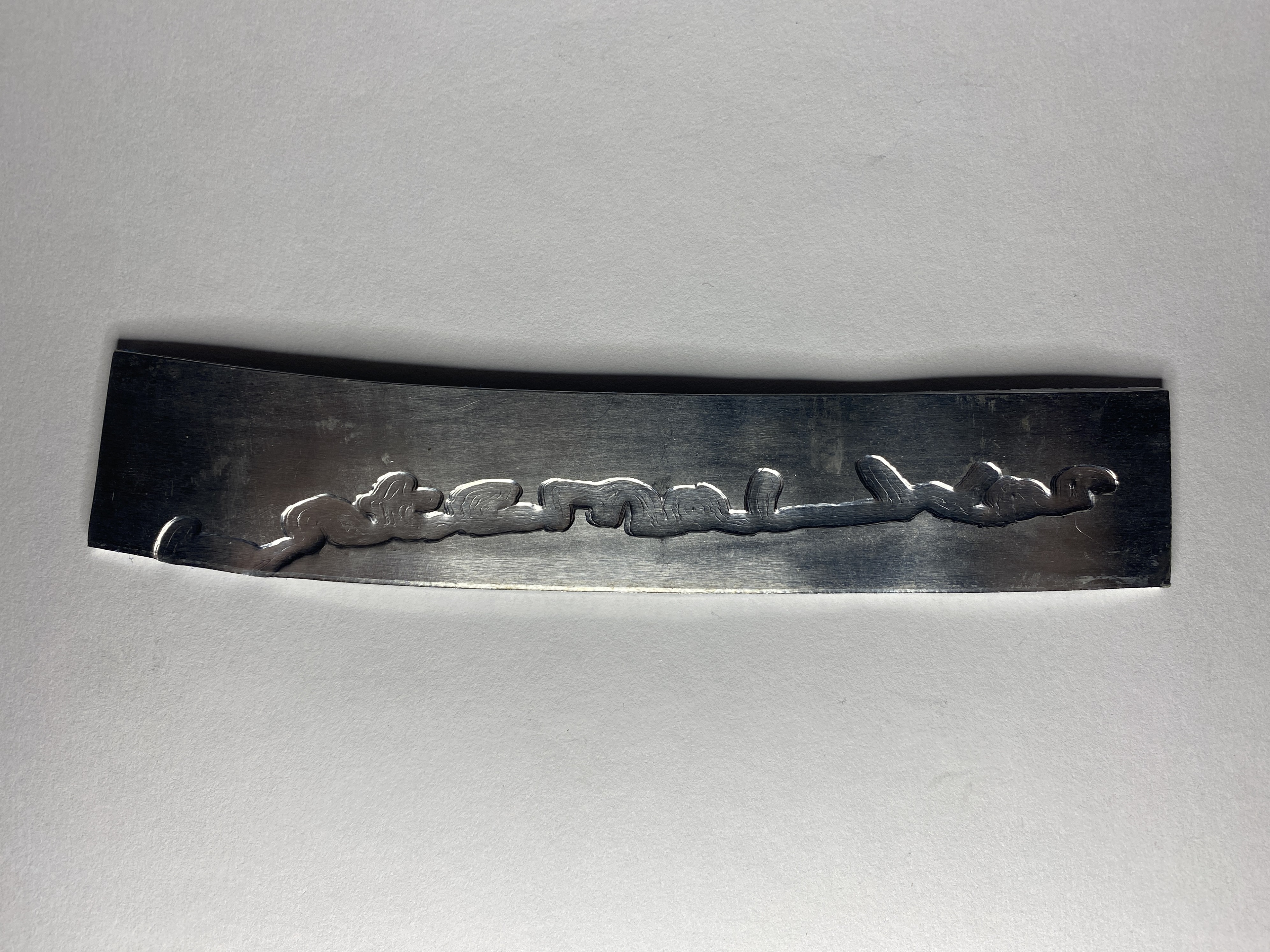
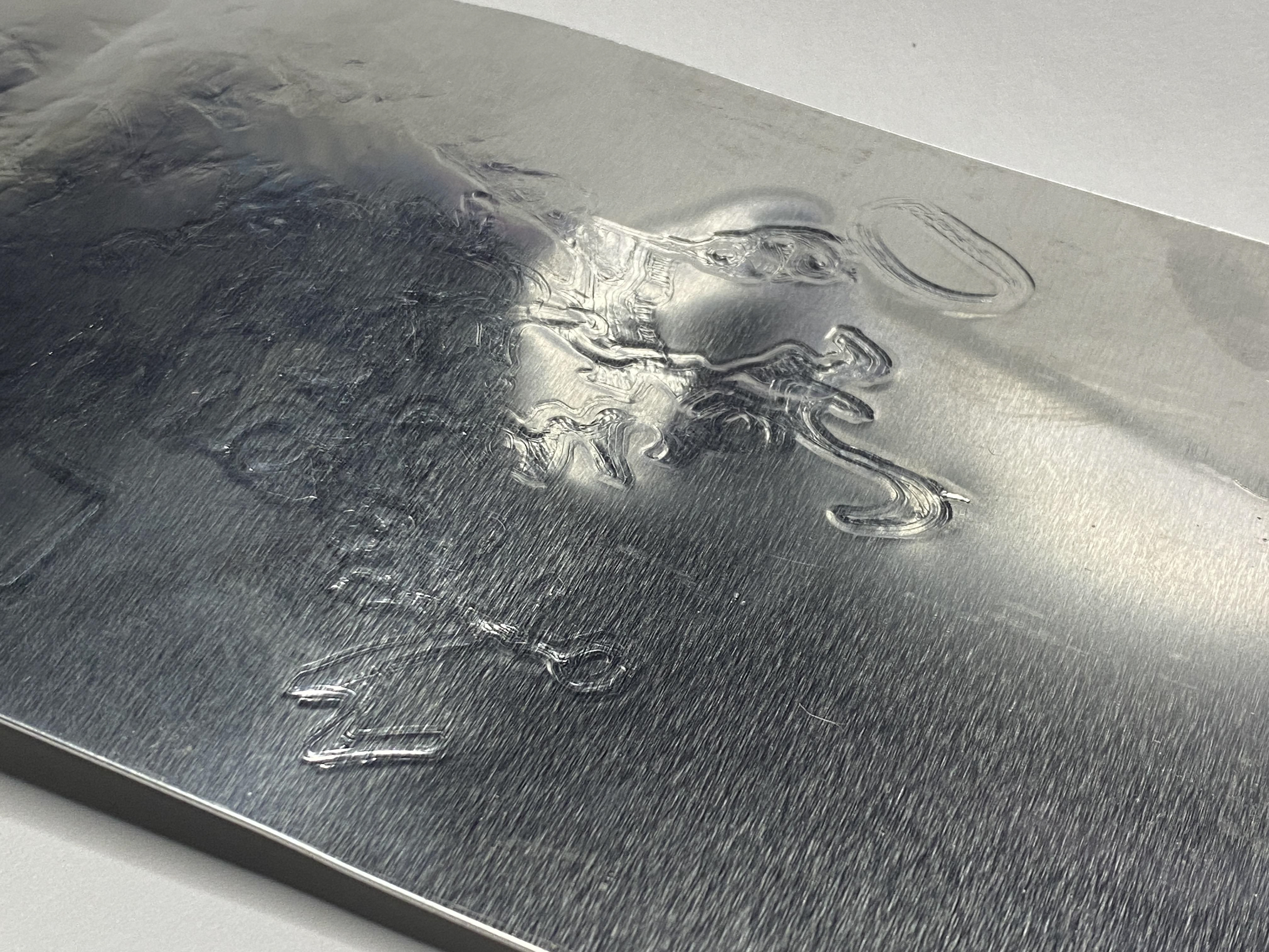
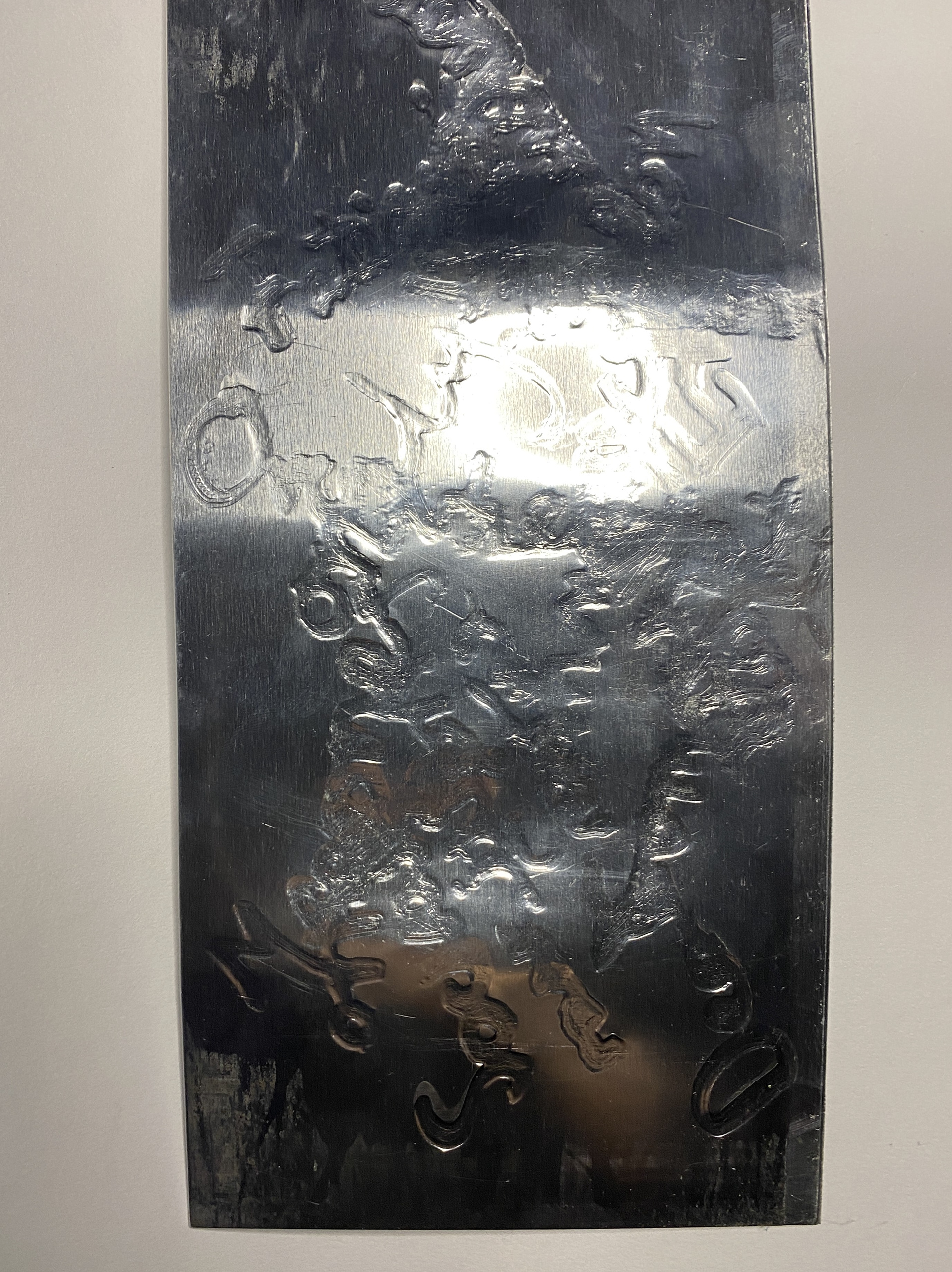
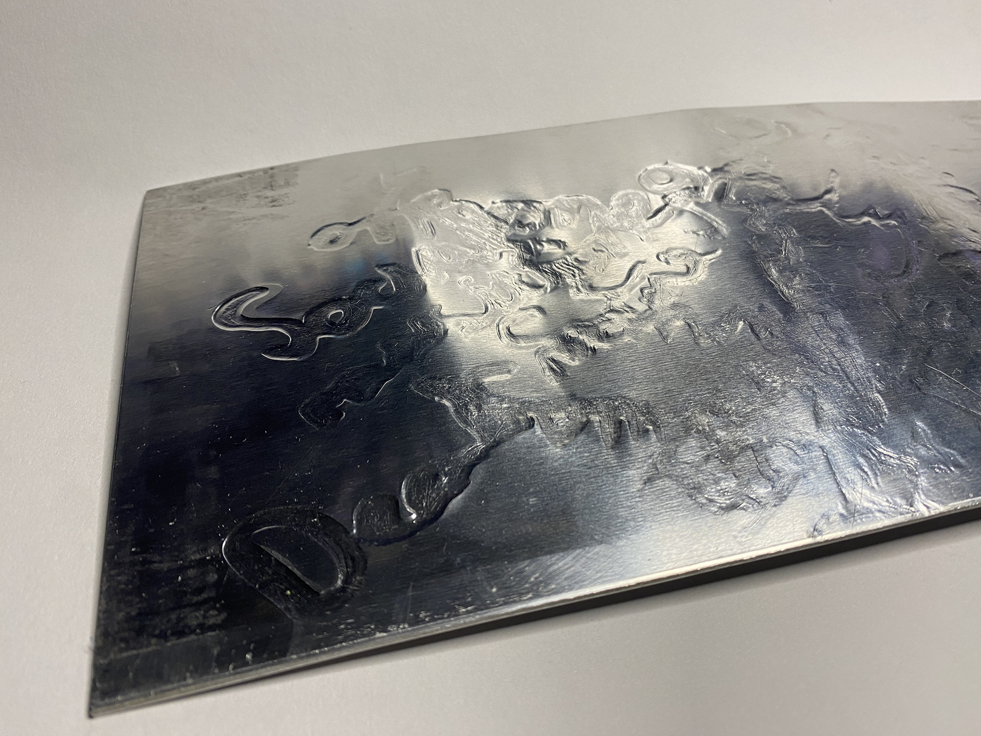
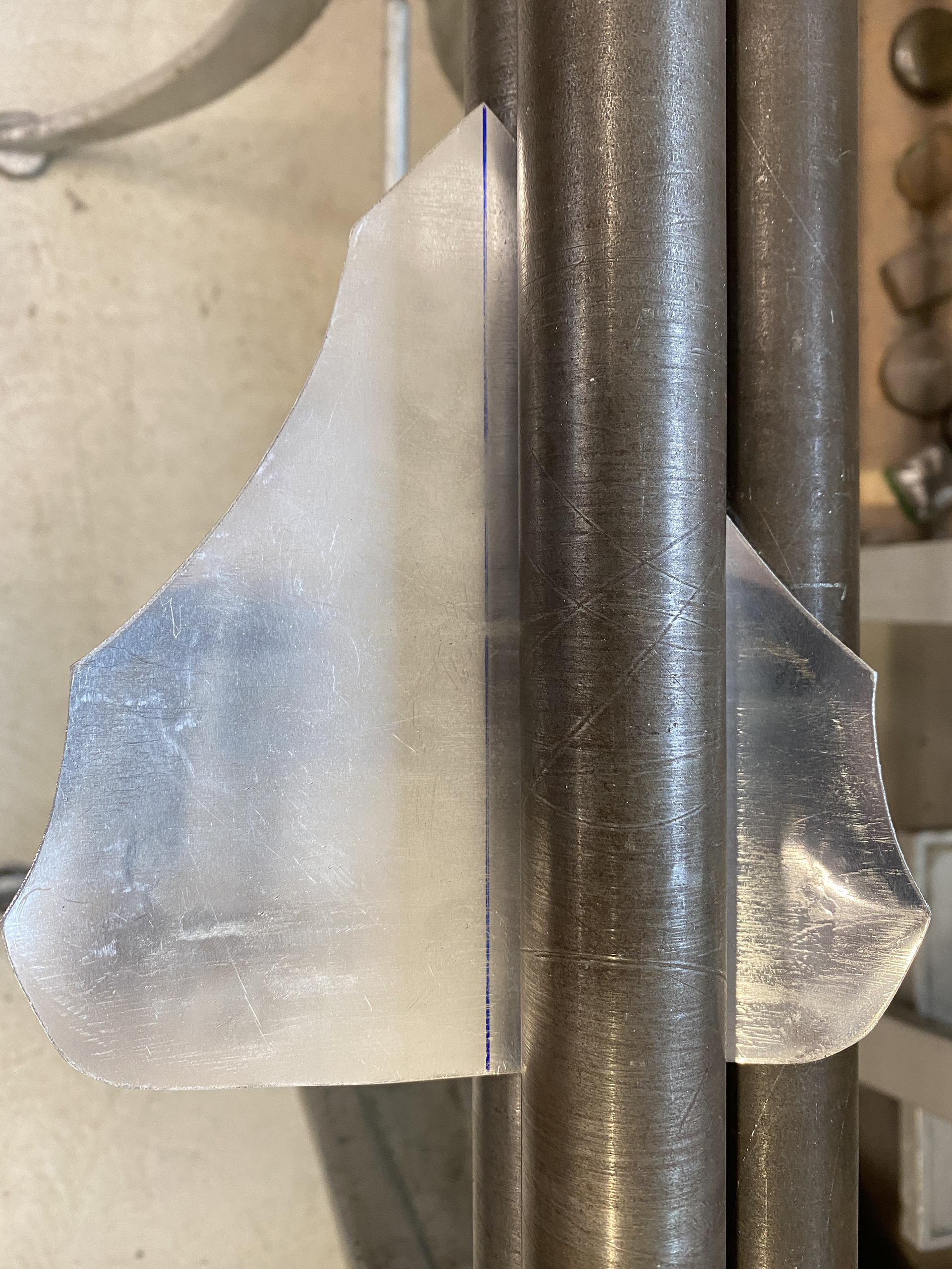
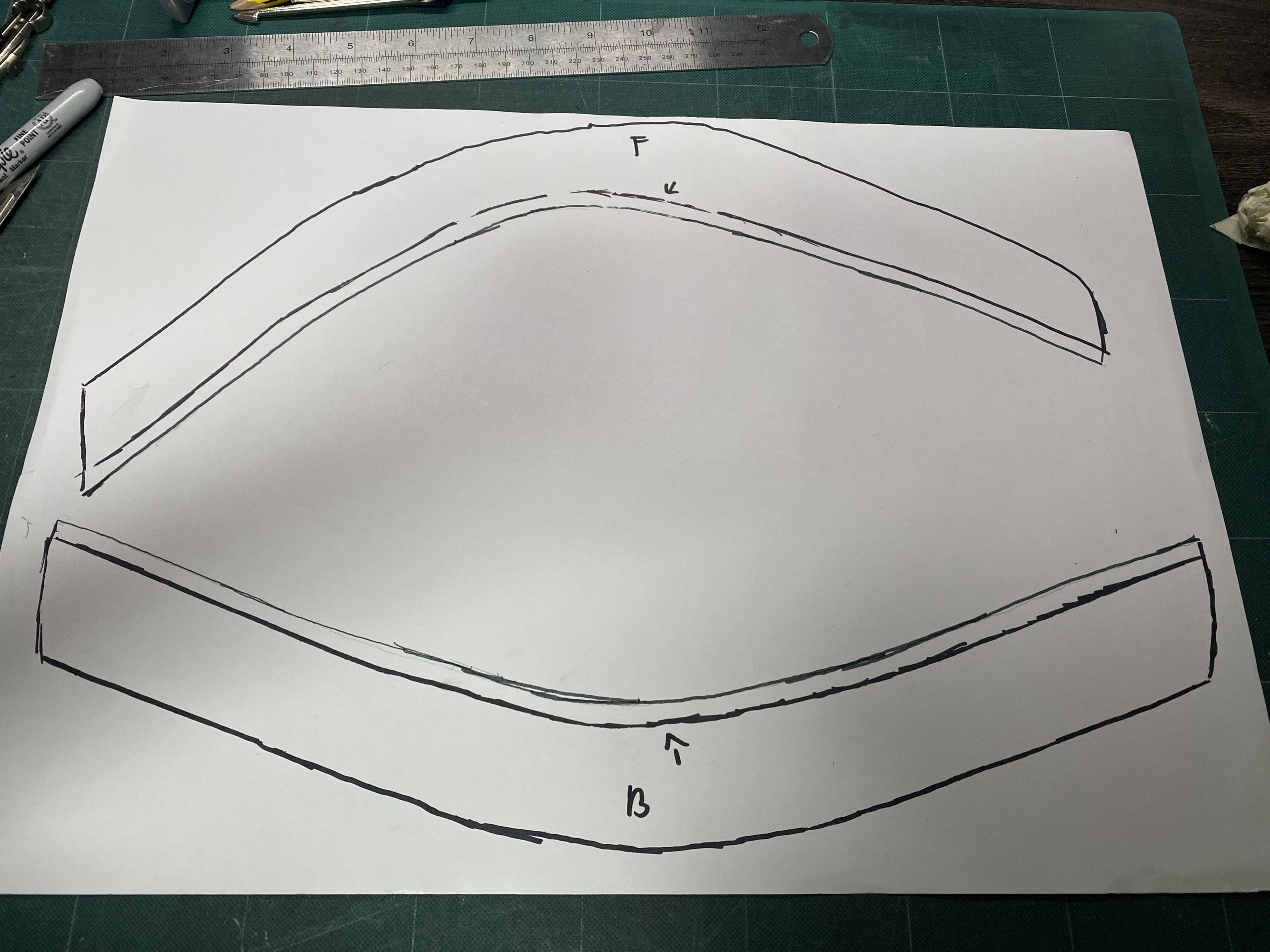
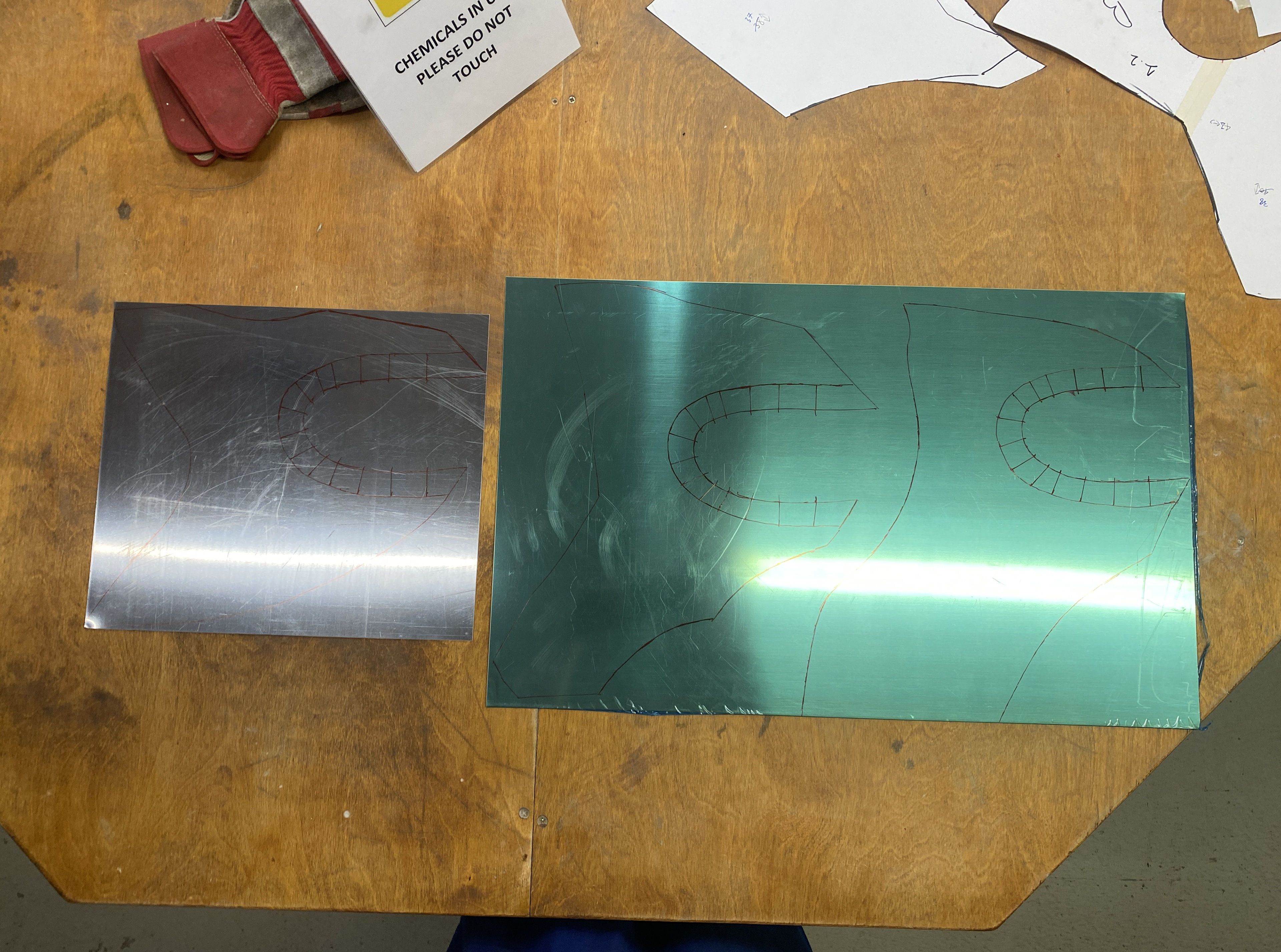
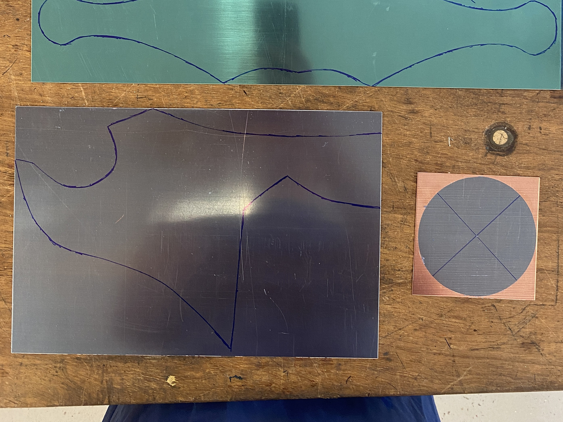
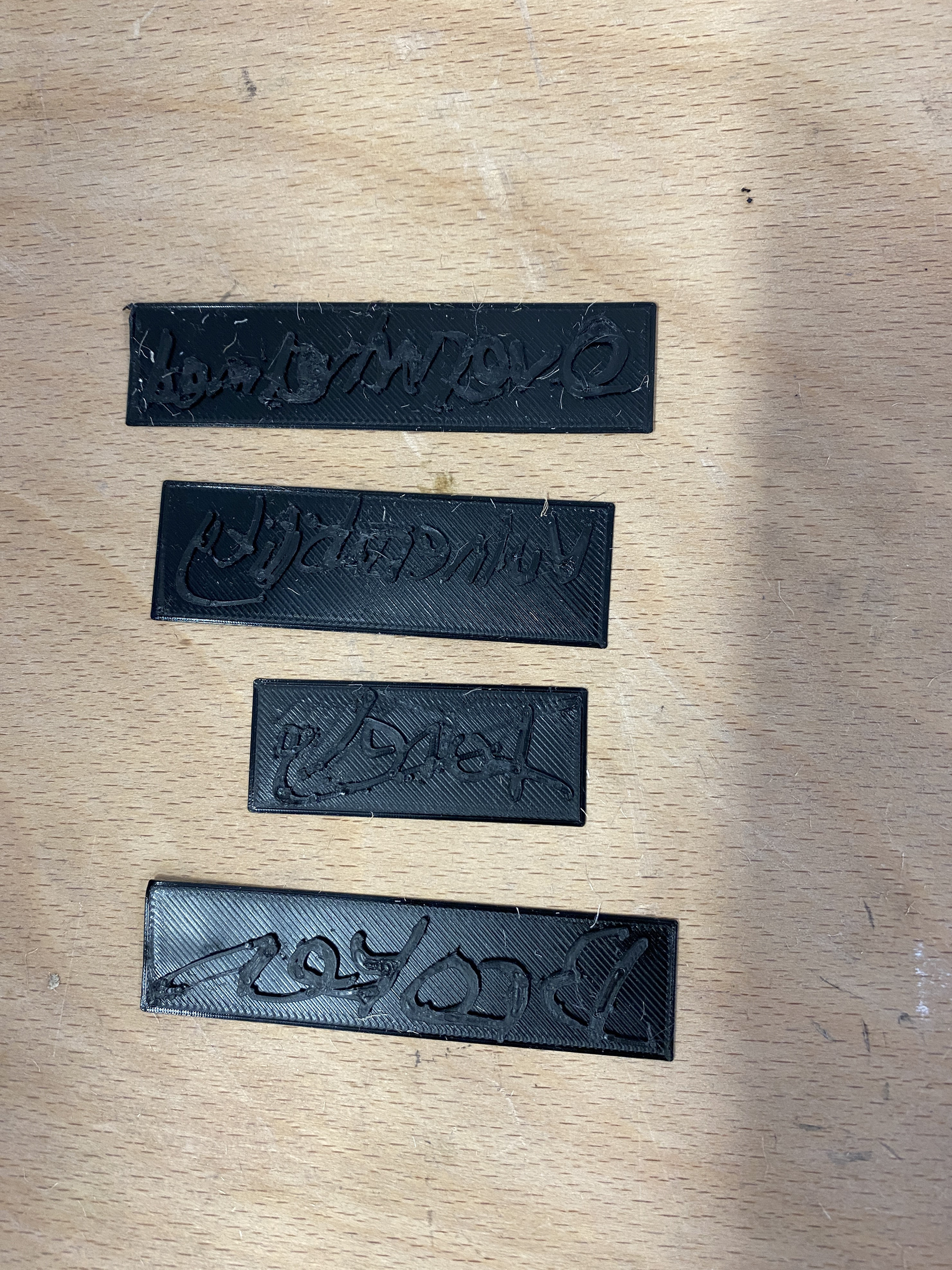
Testing rolling text into sheet metal
0.7mm 1mm 2mm 3mm
I repeated the material thickness tests with aluminium and 3D printed rolling process. I found that 1mm was the best thinner option as it shows the transferred text well but doesn’t deform too much like the 0.7mm. I also prefer the 2mm over the 3mm, as the 3mm was too bulky and wouldn’t be as easy to form into complex shapes.

1mm Thickness
2mm Thickness
Continuing the thickness tests, I experimented with rolling in a larger collage of text into aluminium and found that in this larger format the 2mm material gave more clarity. Therefore, I will use the 1mm for individual lines of text which can easily be moulded over copper and brass forms, and 2mm for larger sheet.
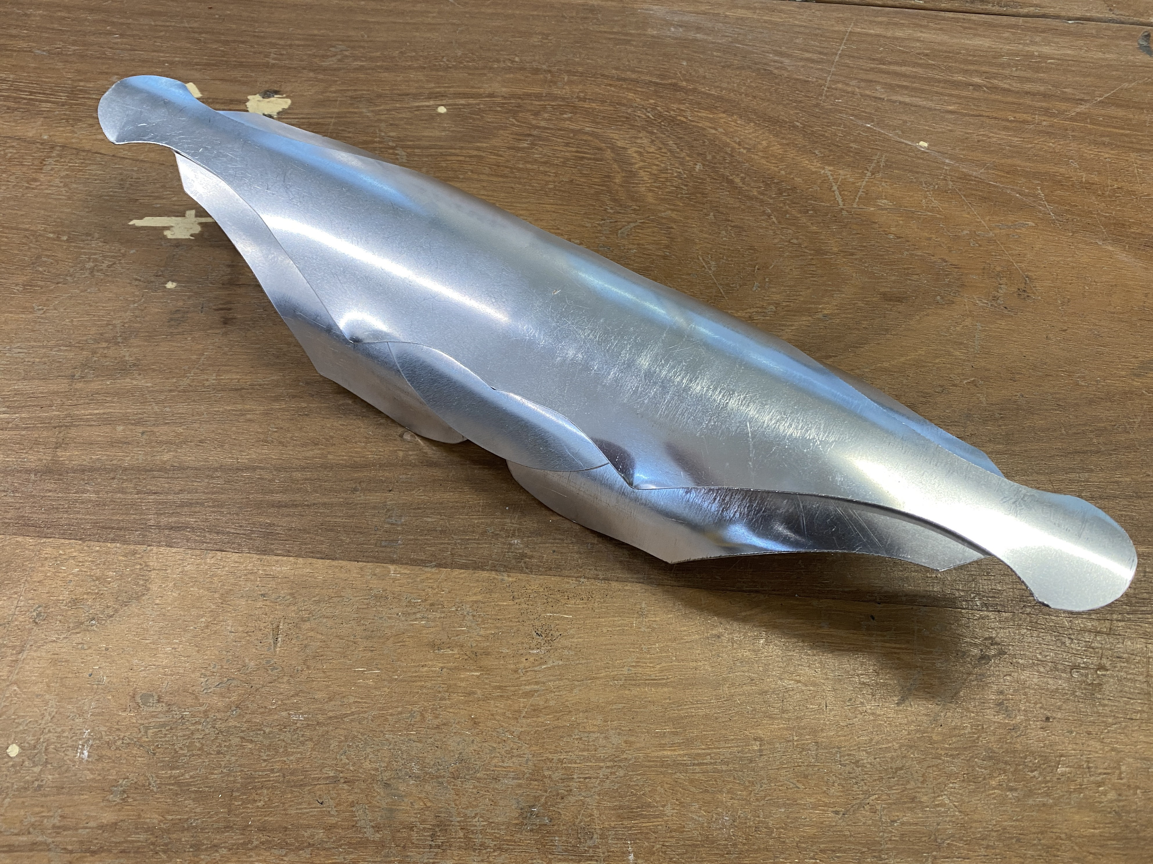
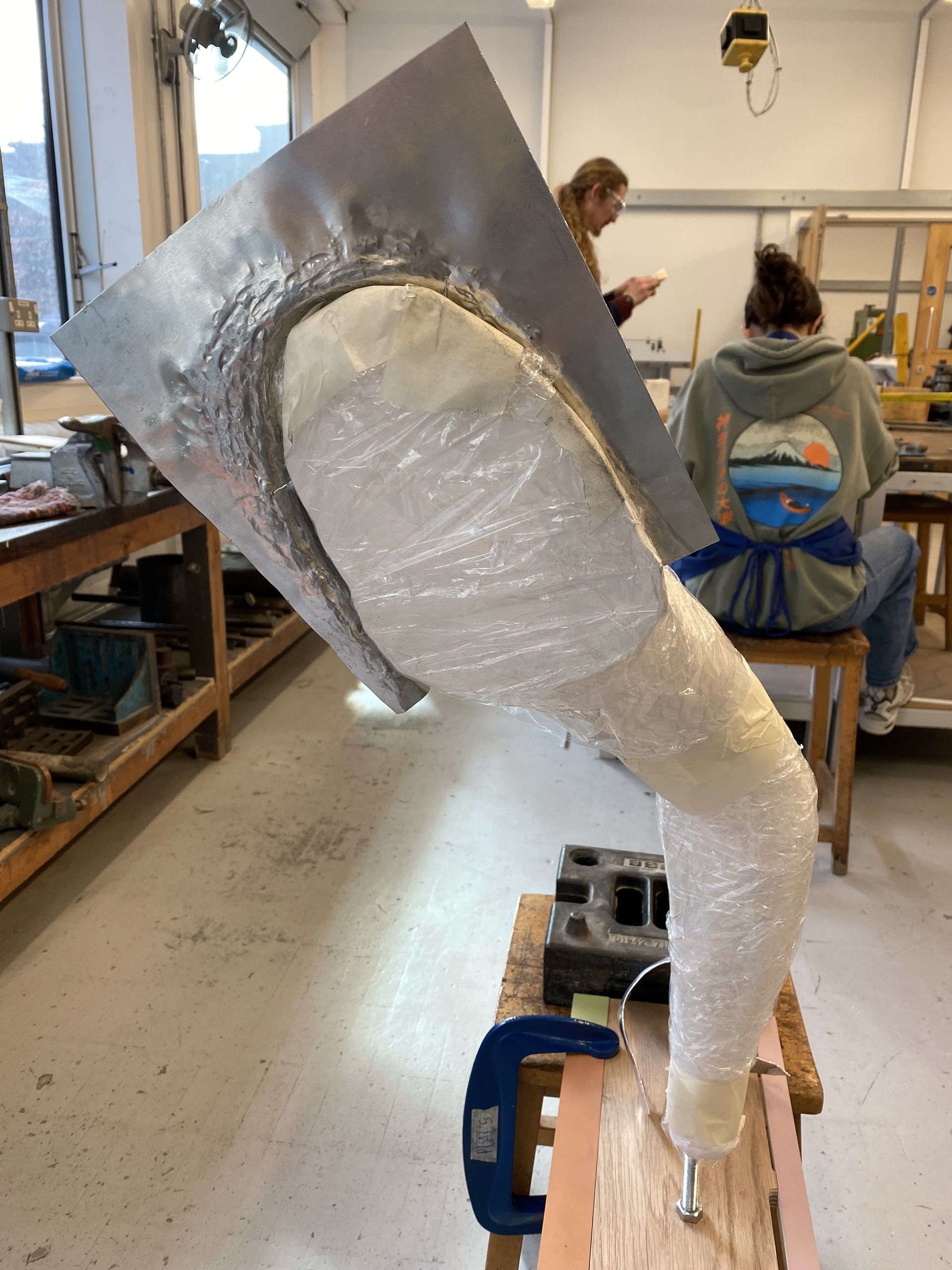
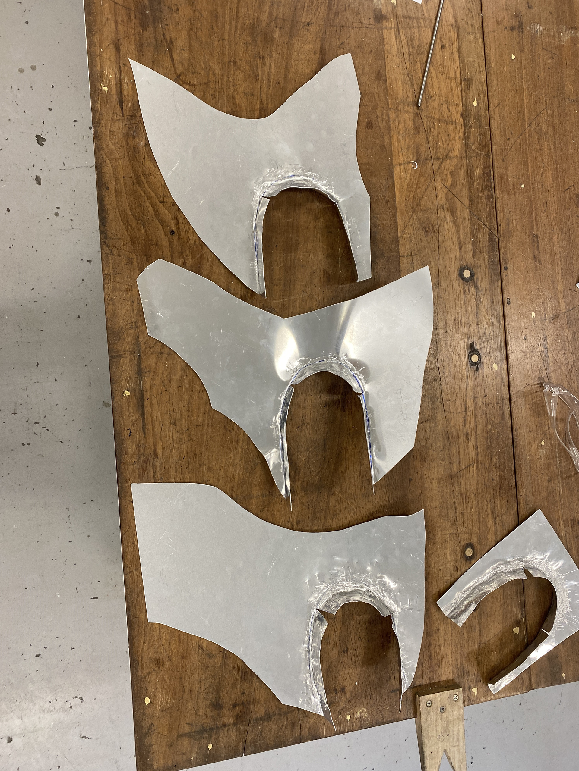
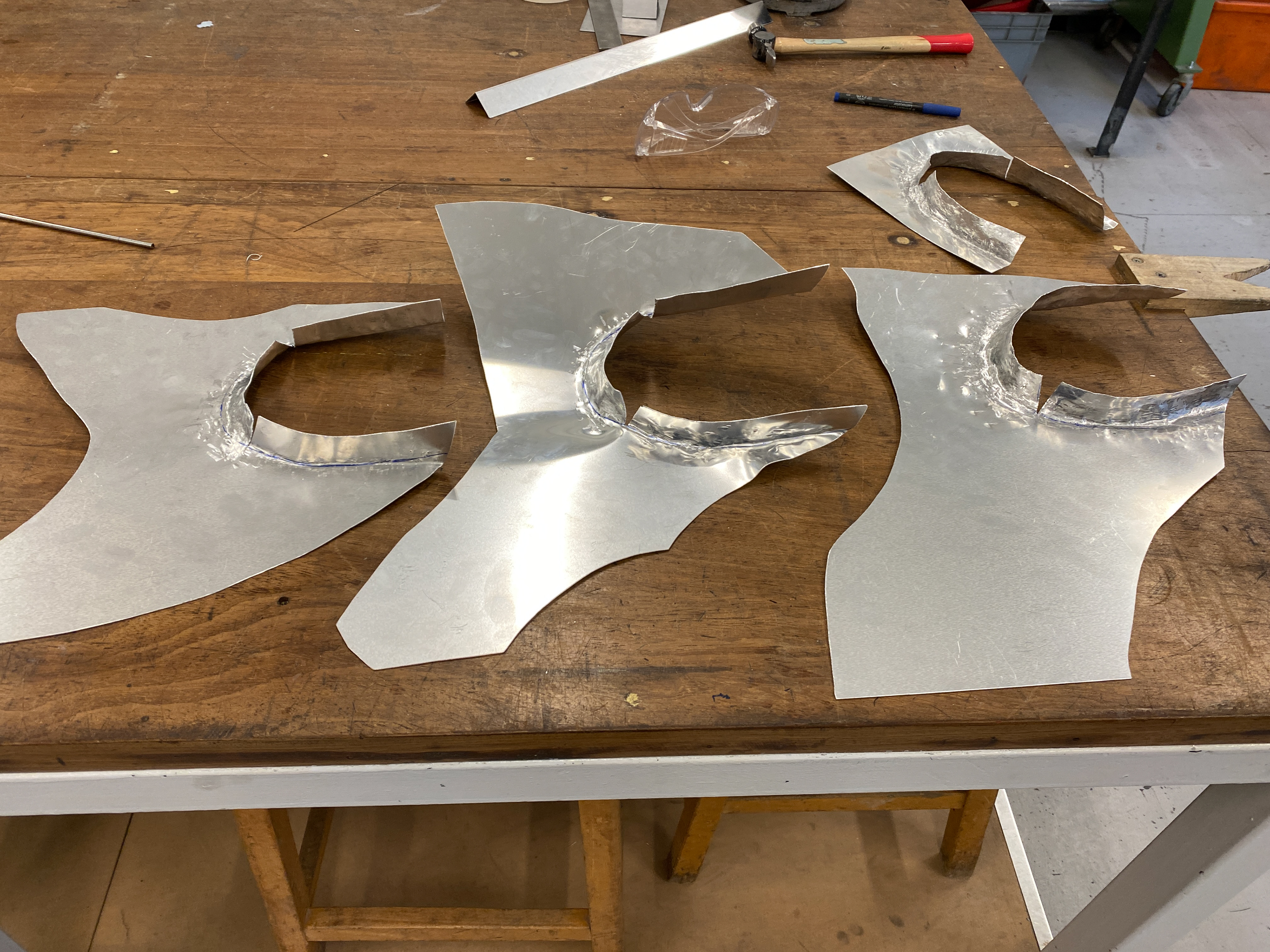
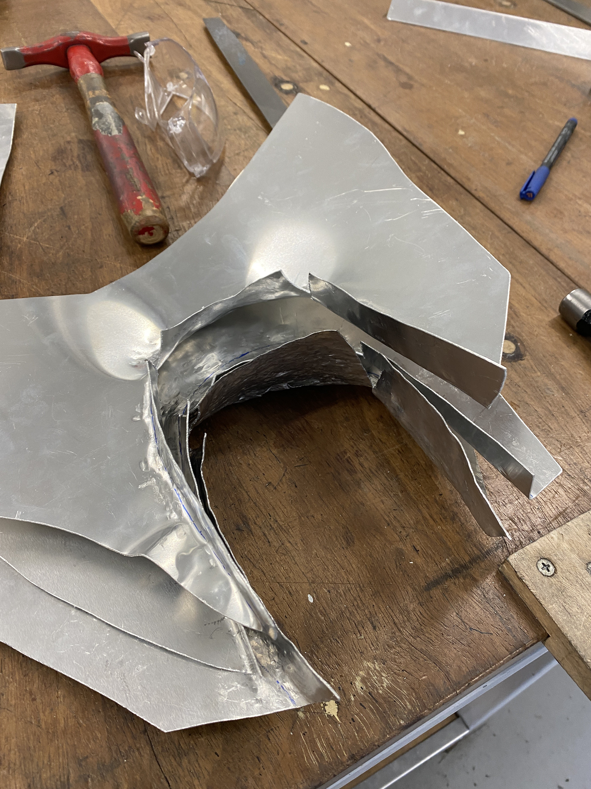
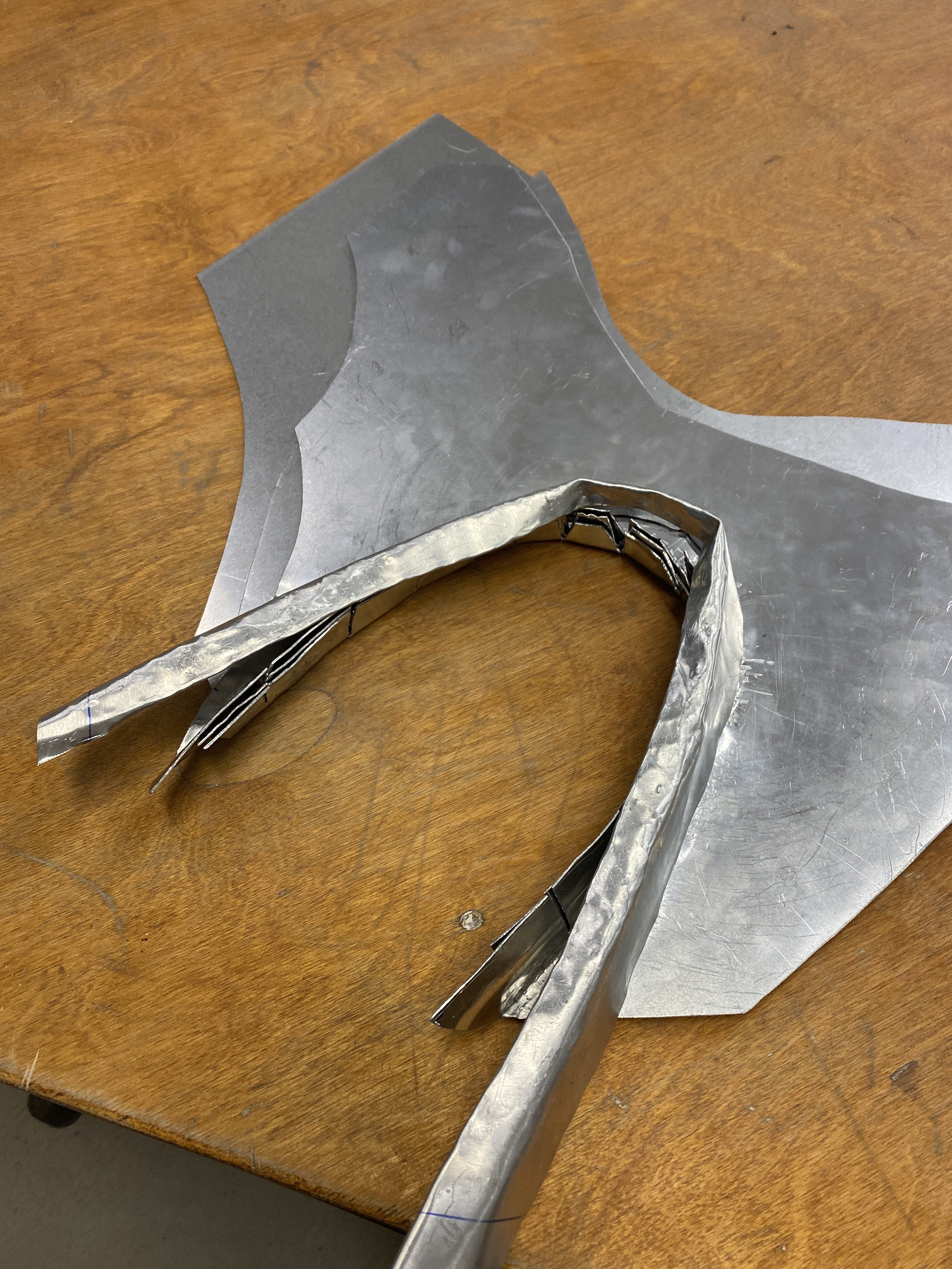
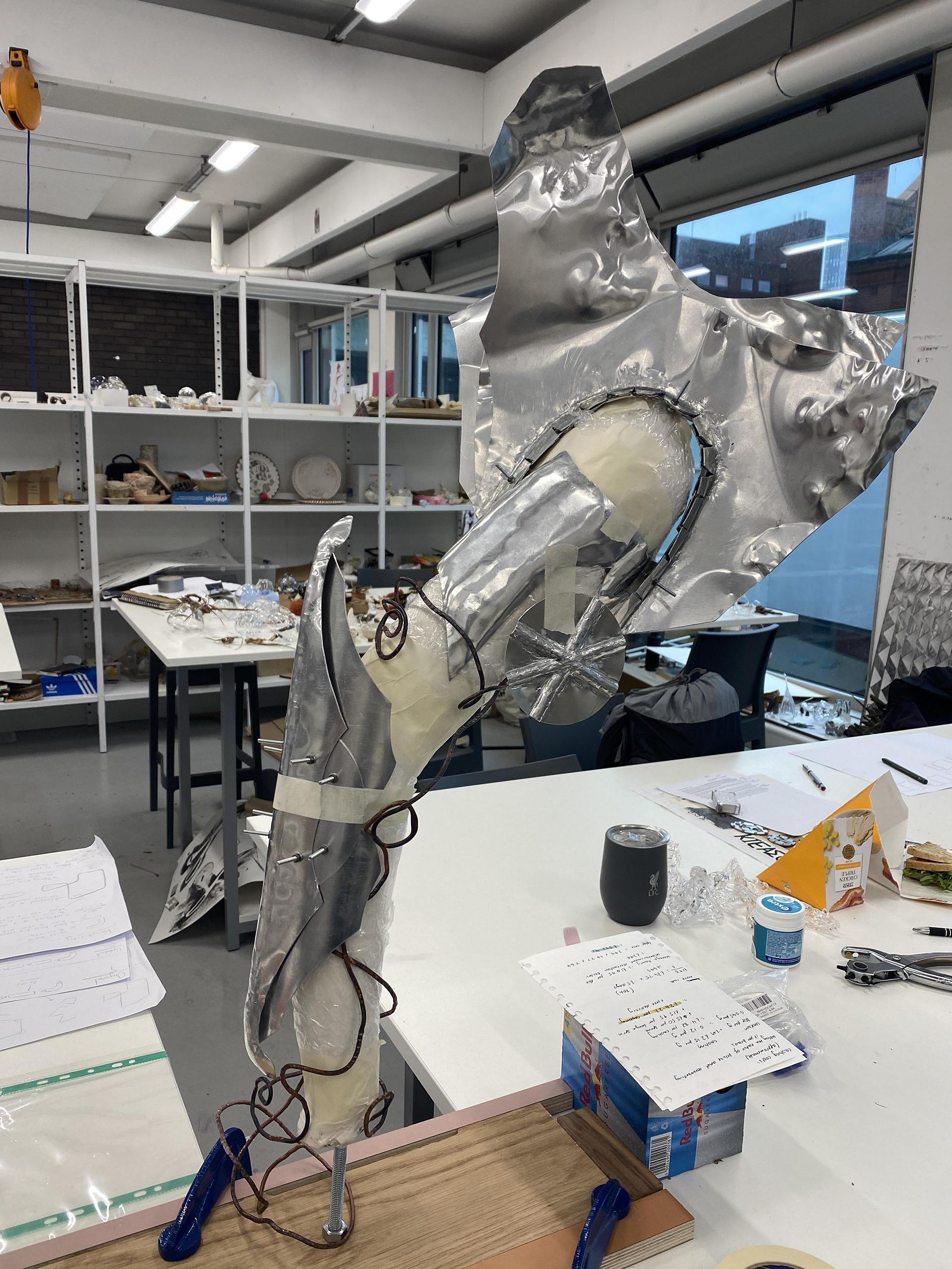
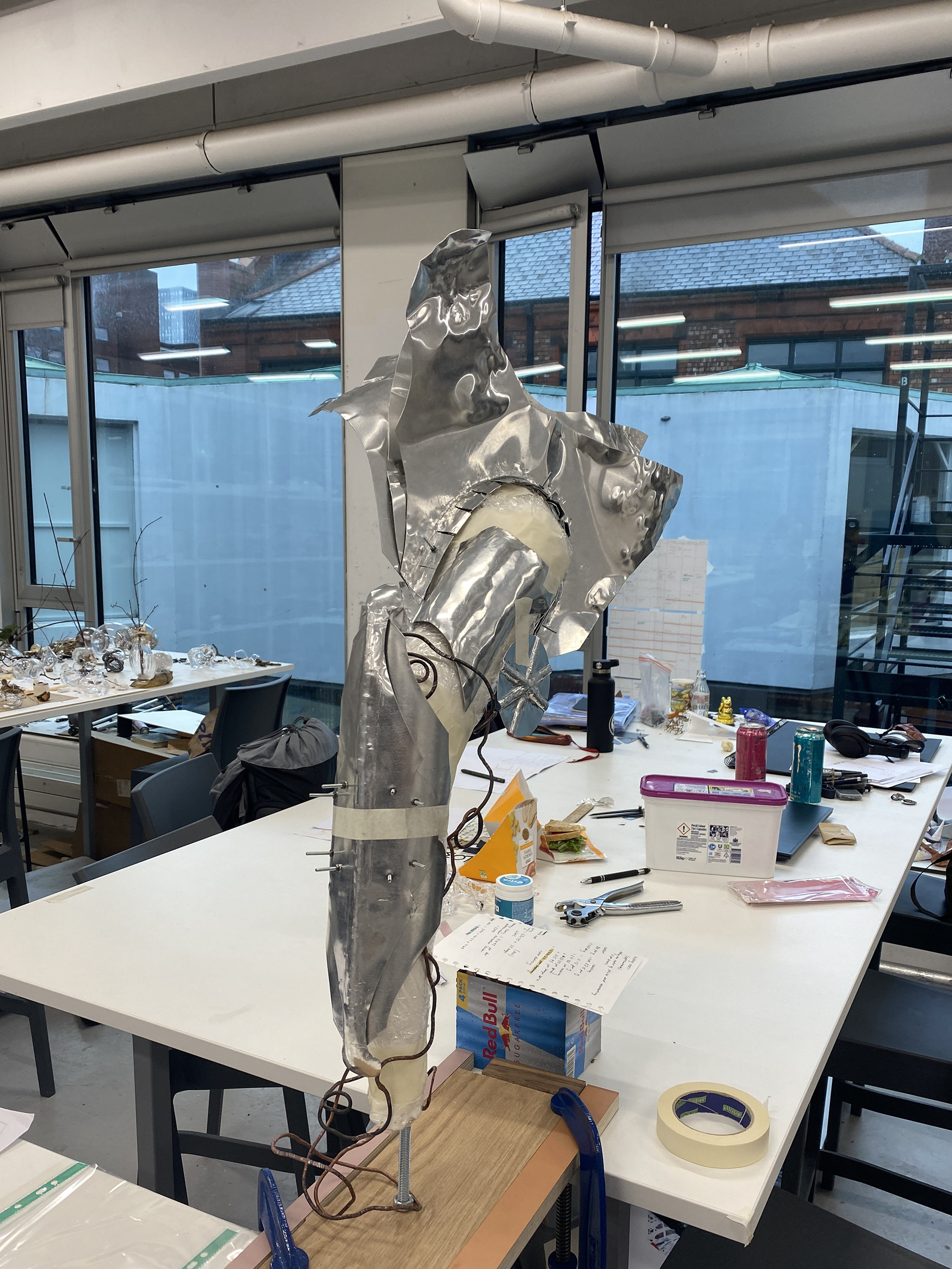
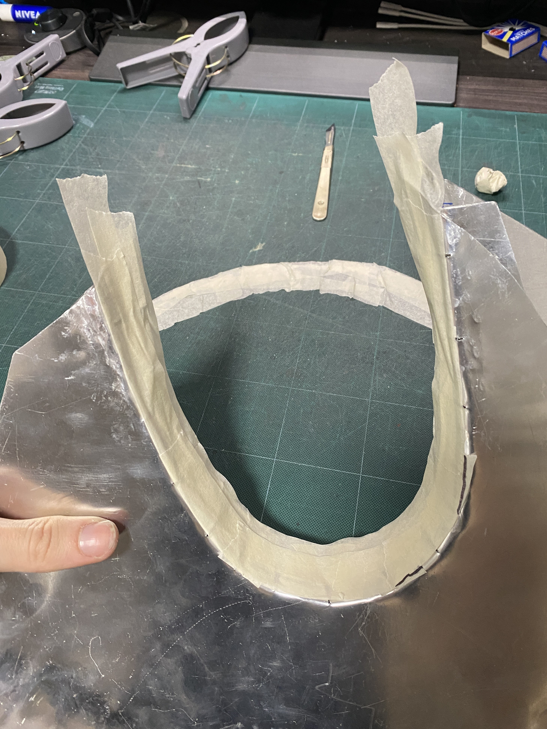
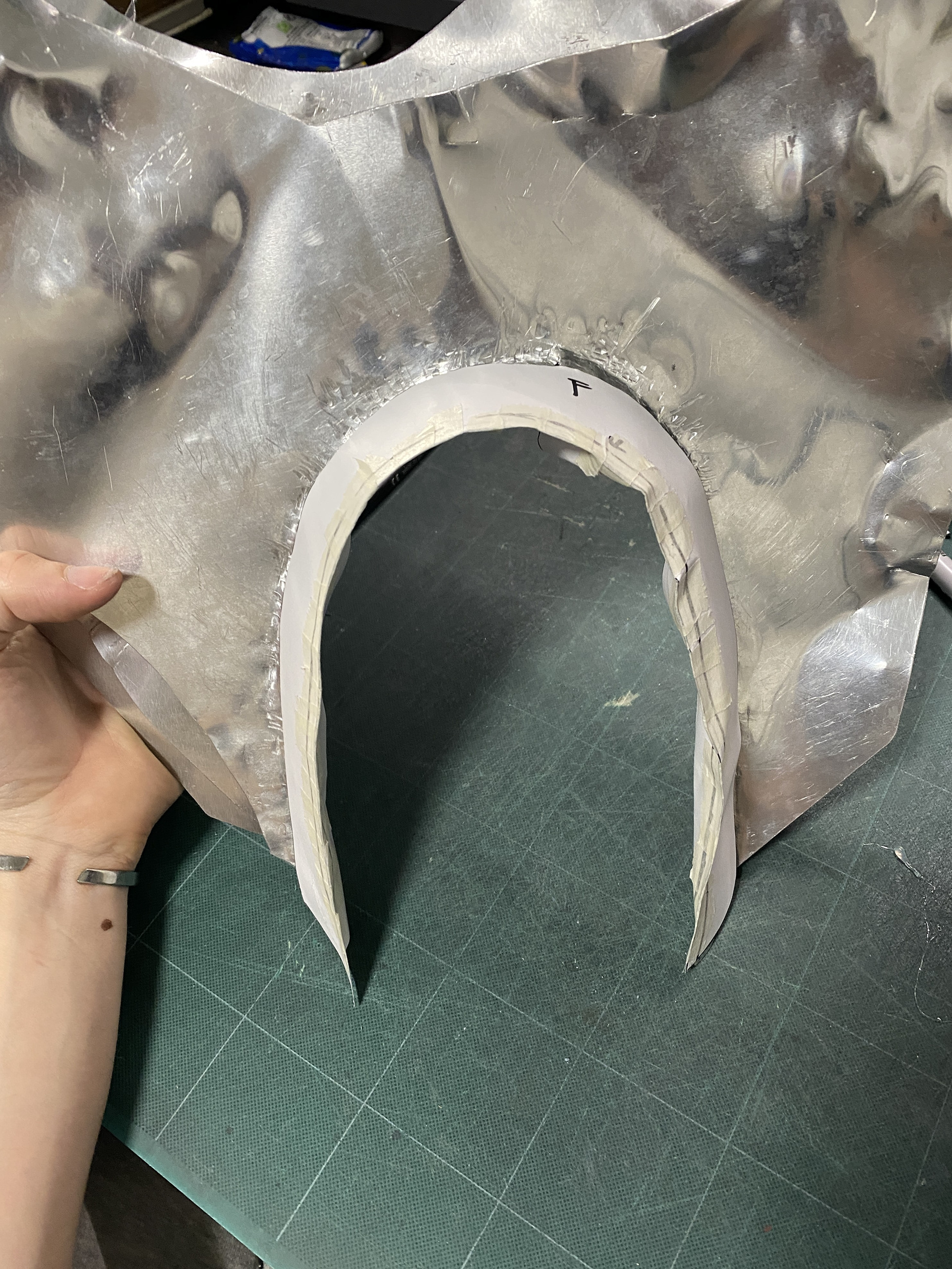
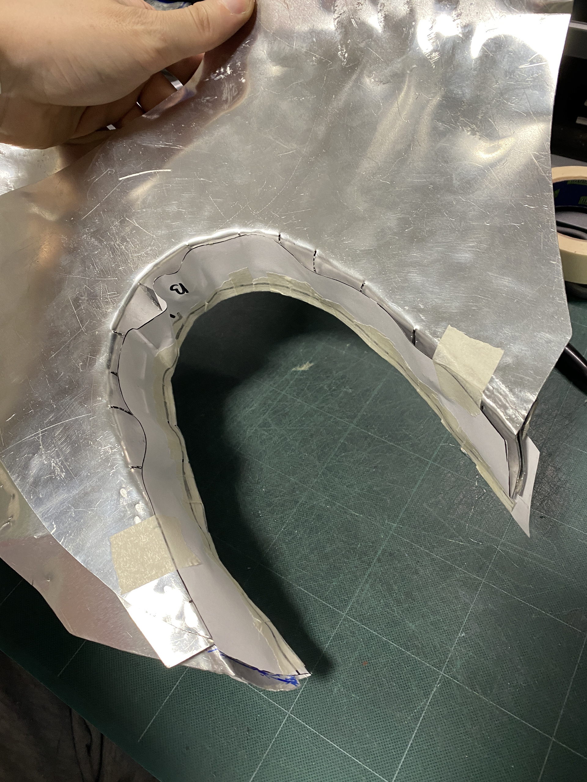
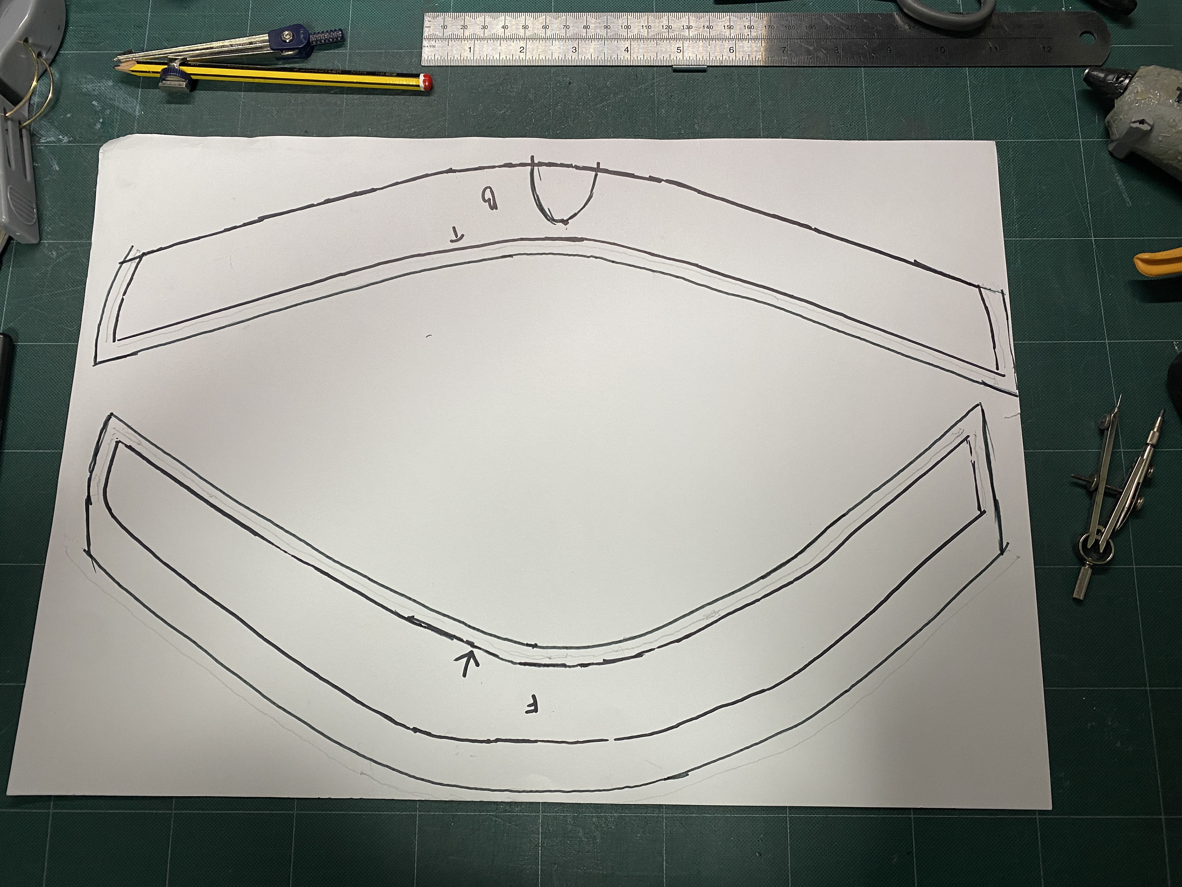
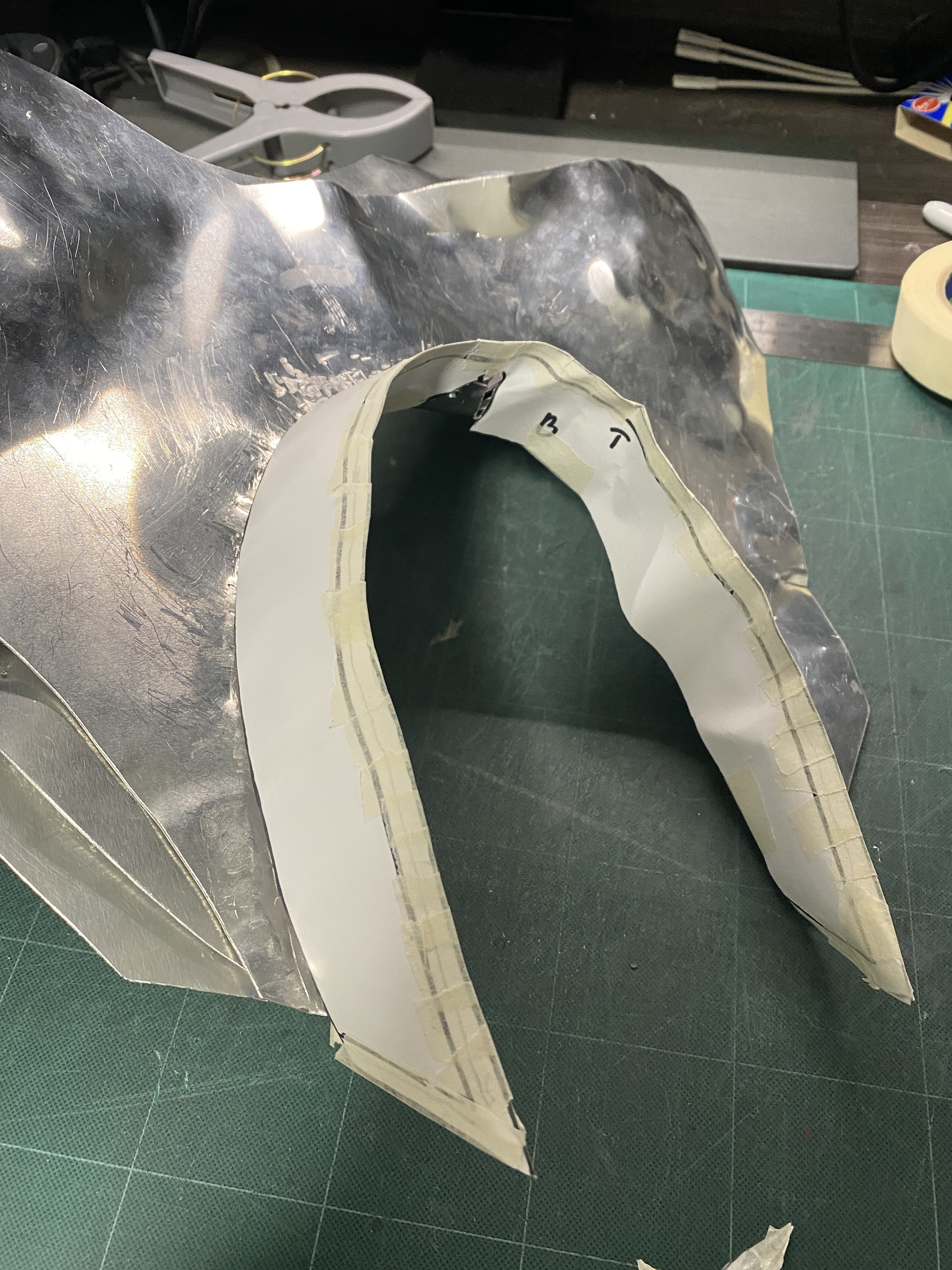
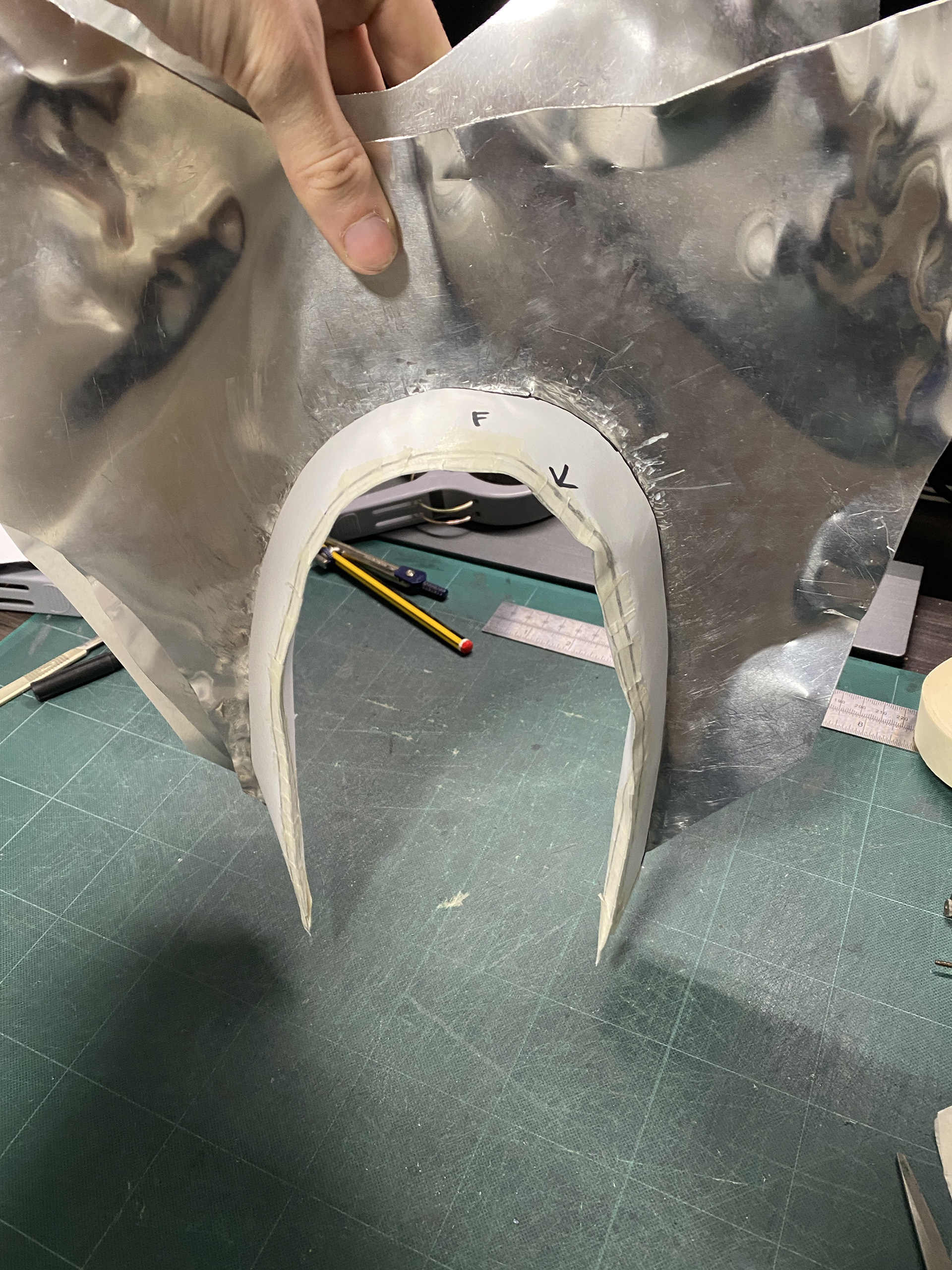
Aluminium elbow section modelling
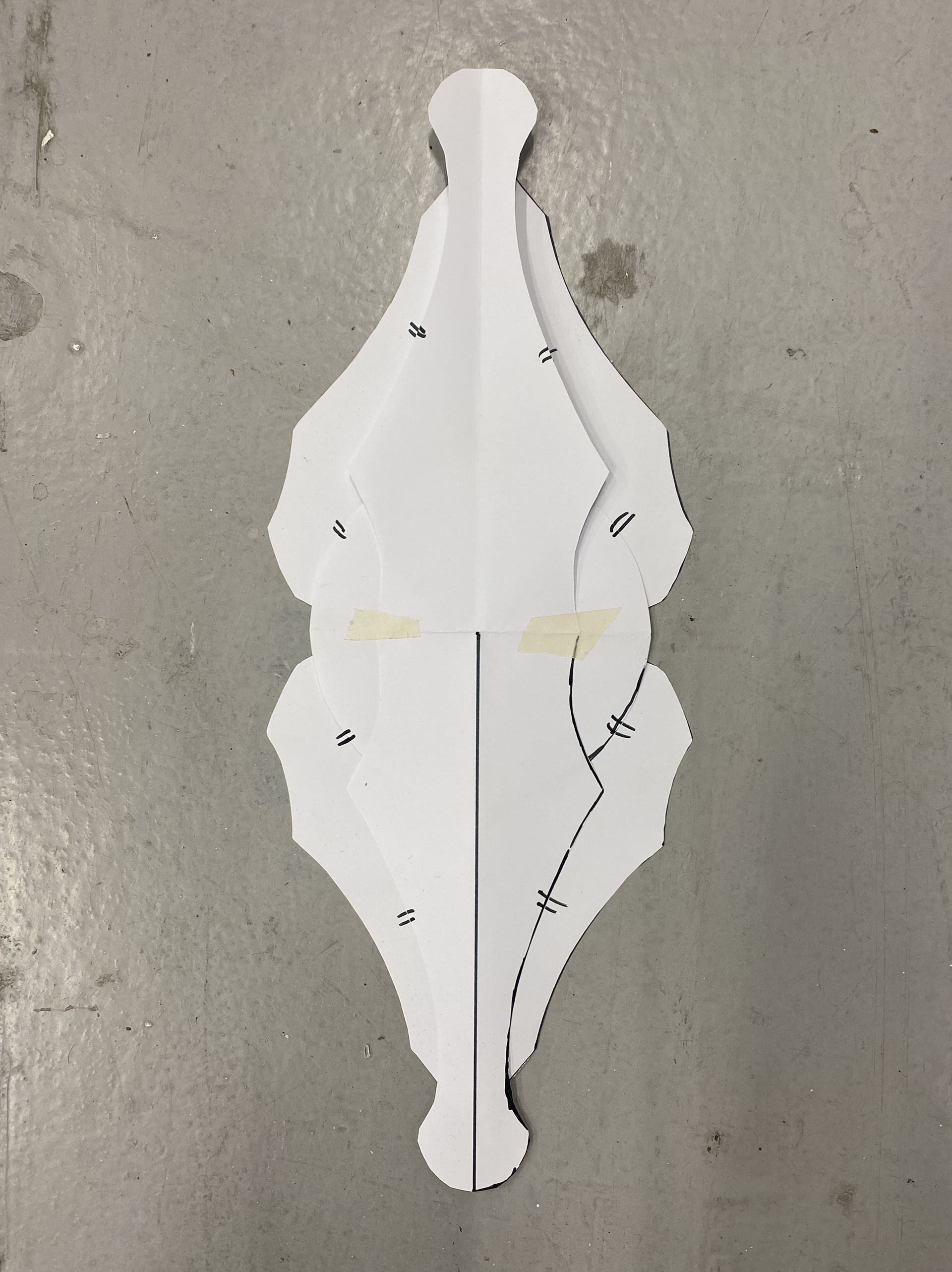
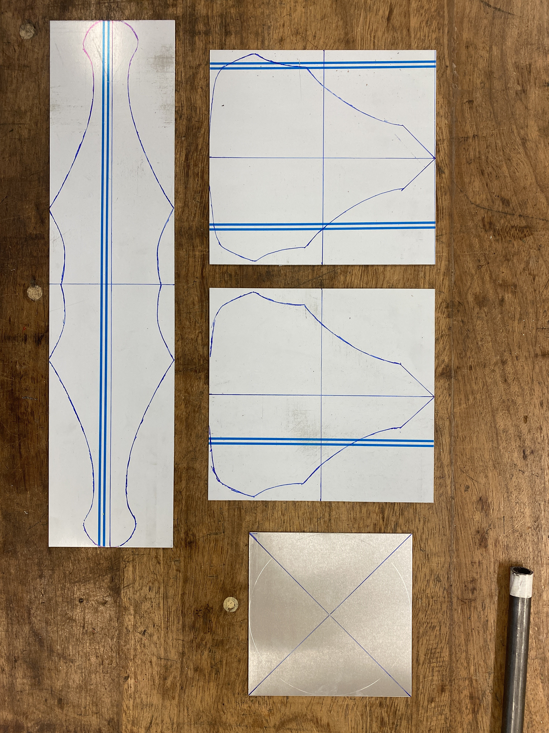
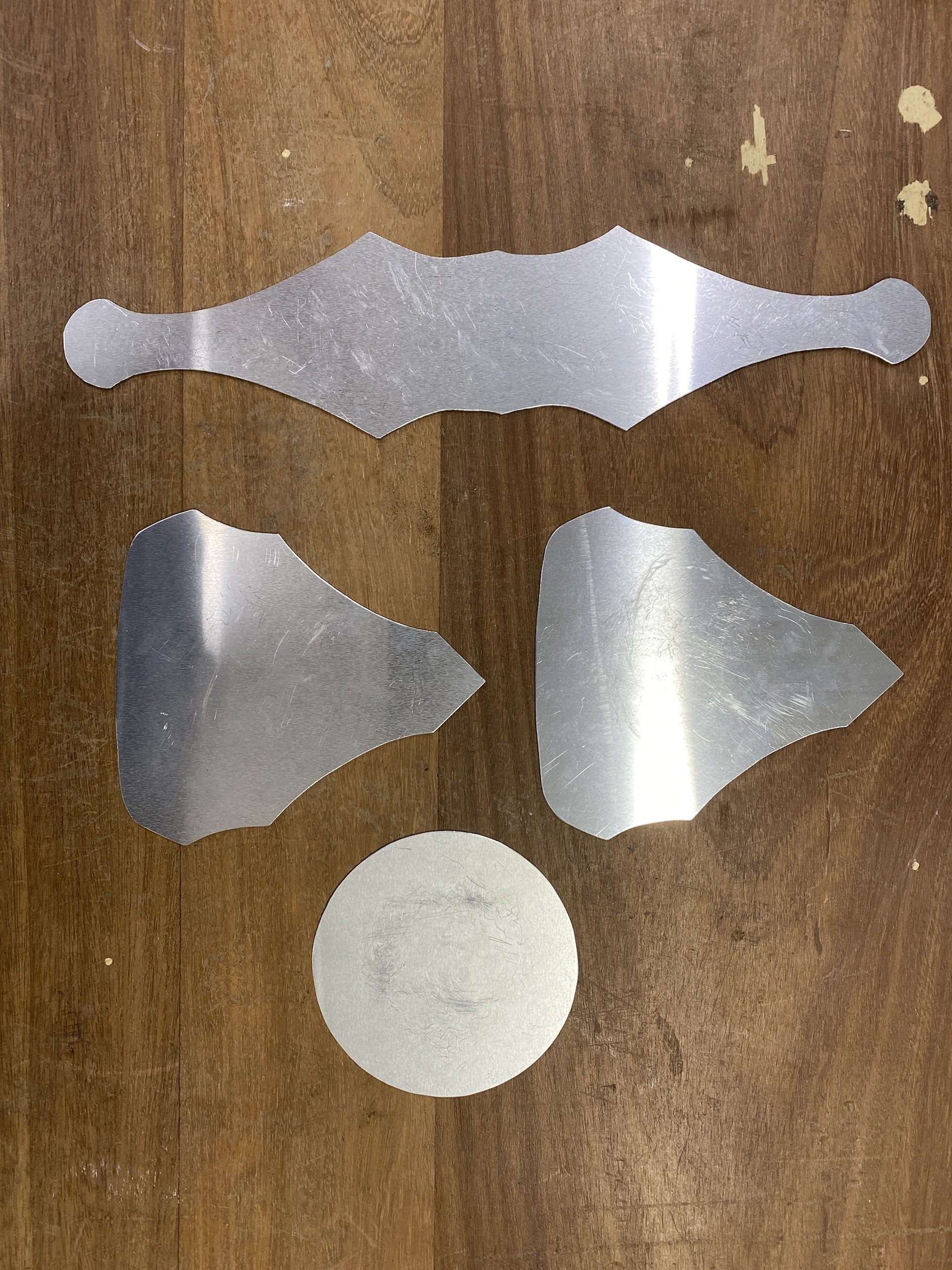
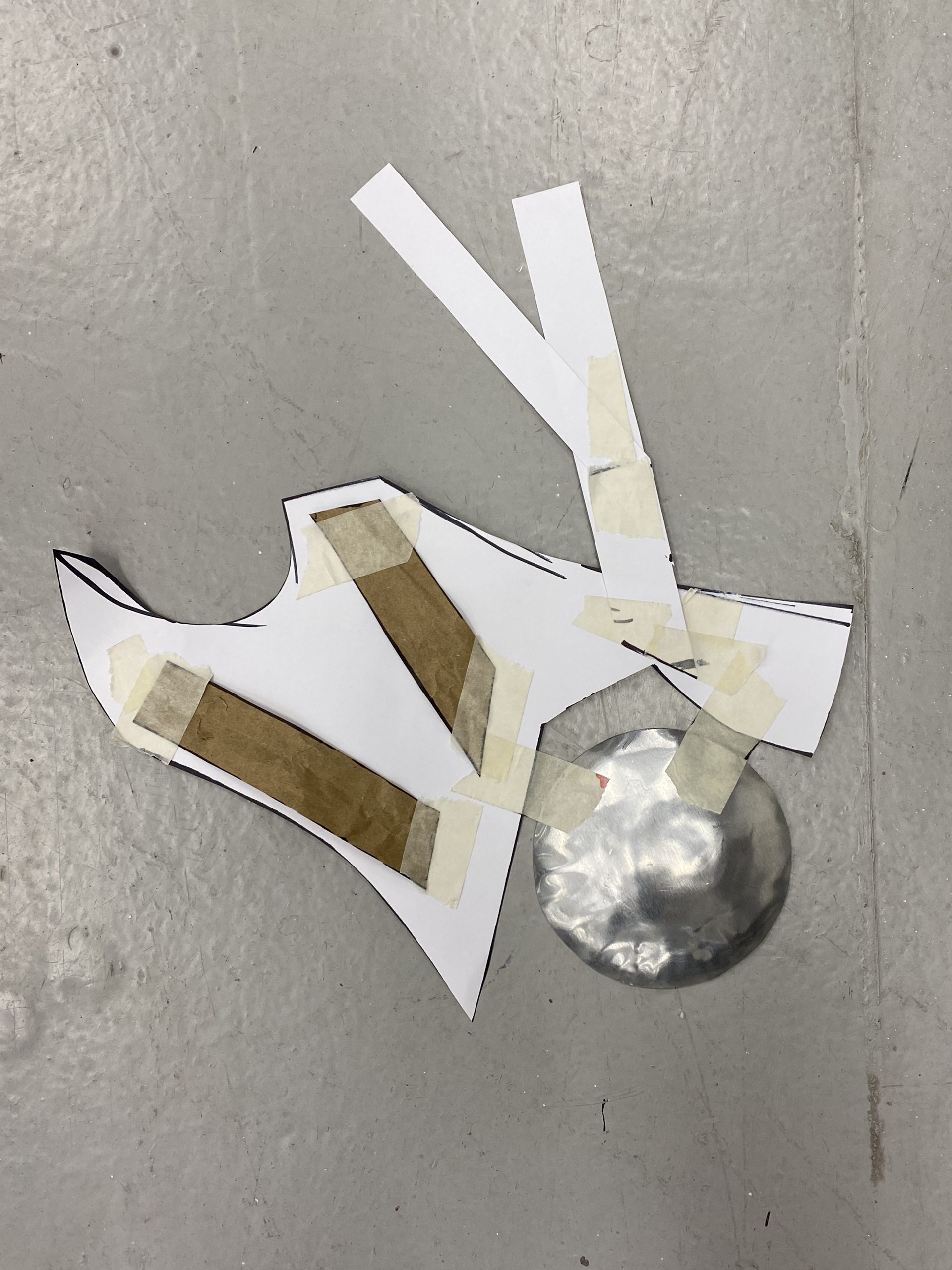
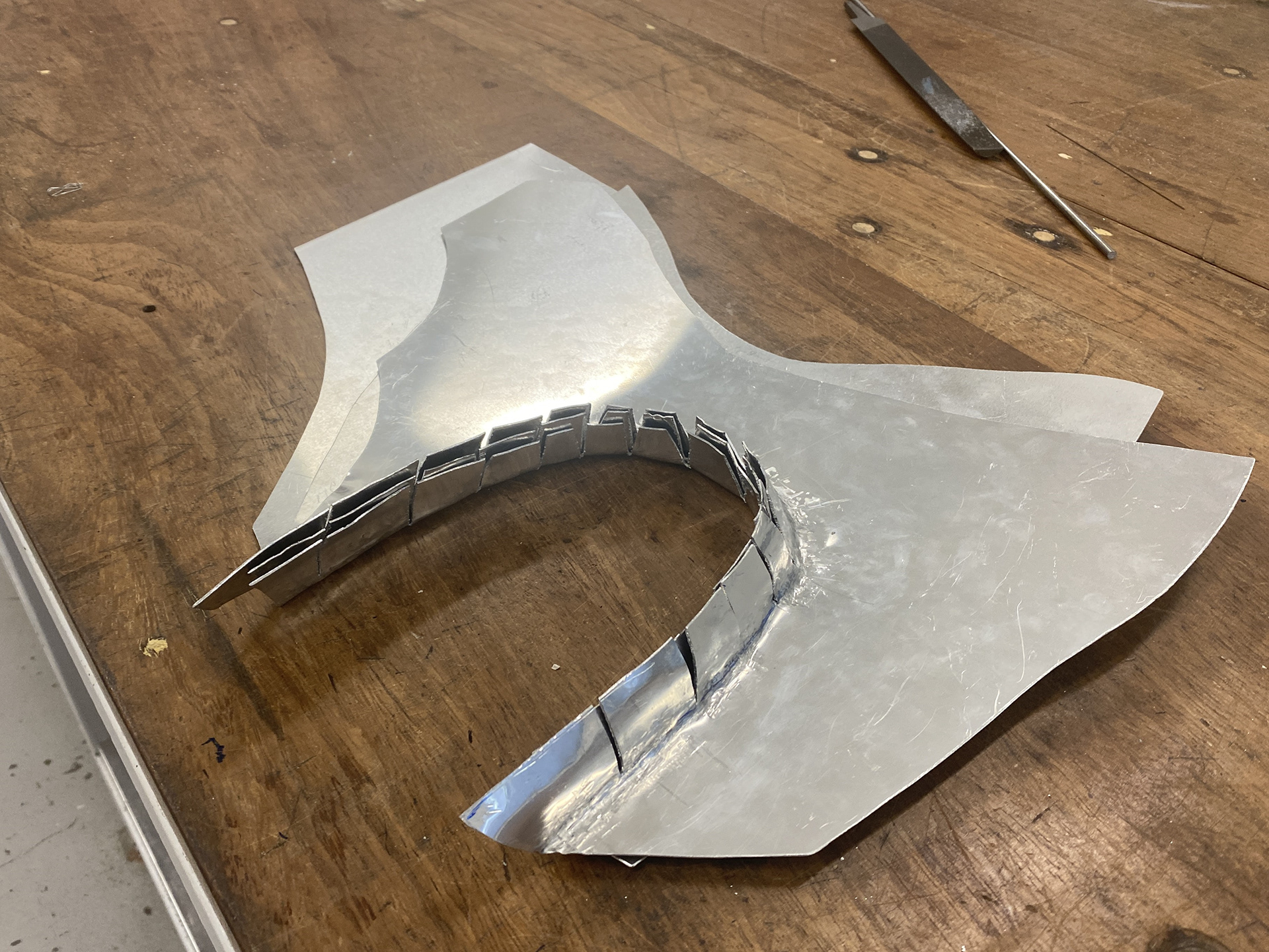
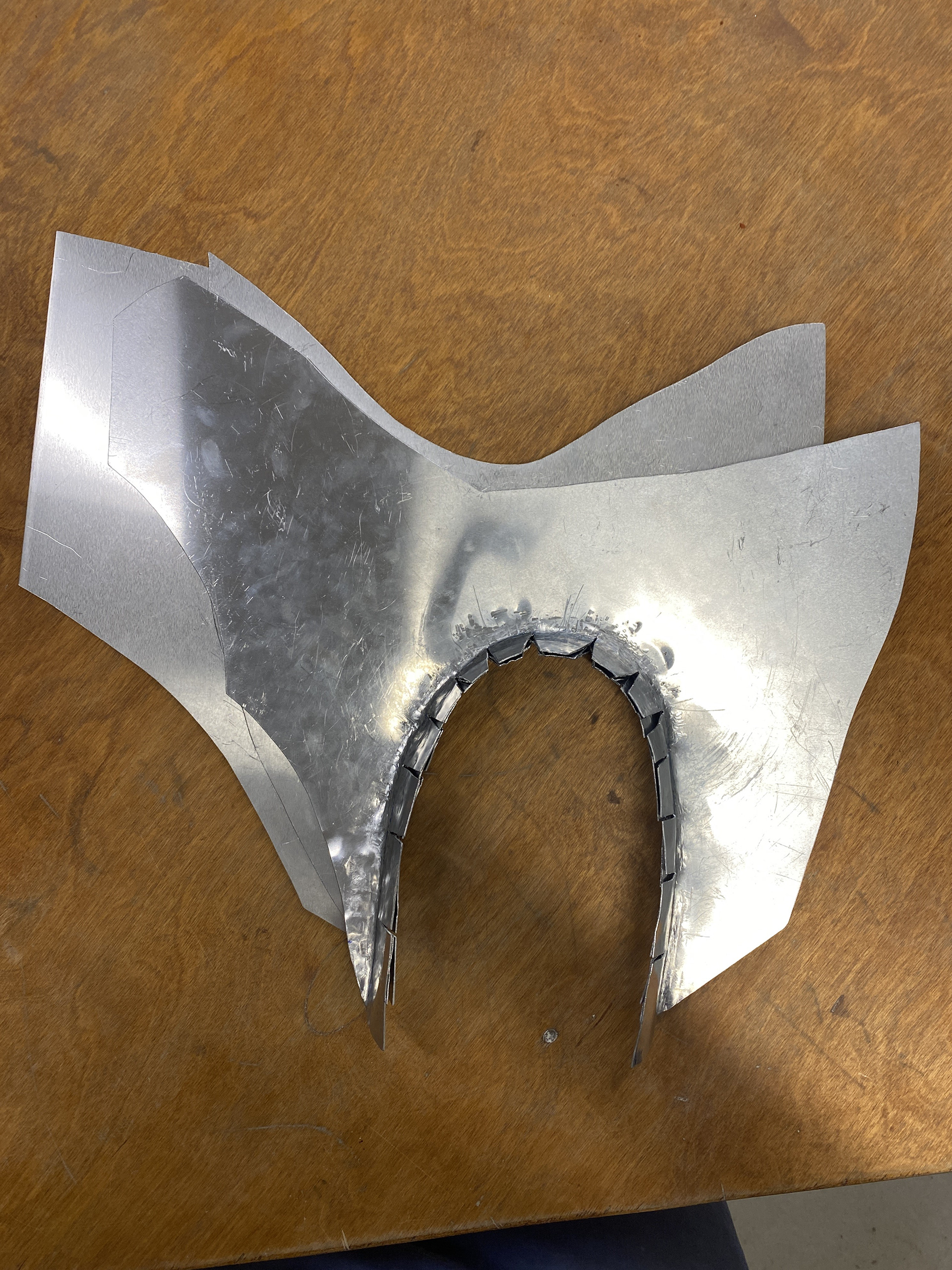
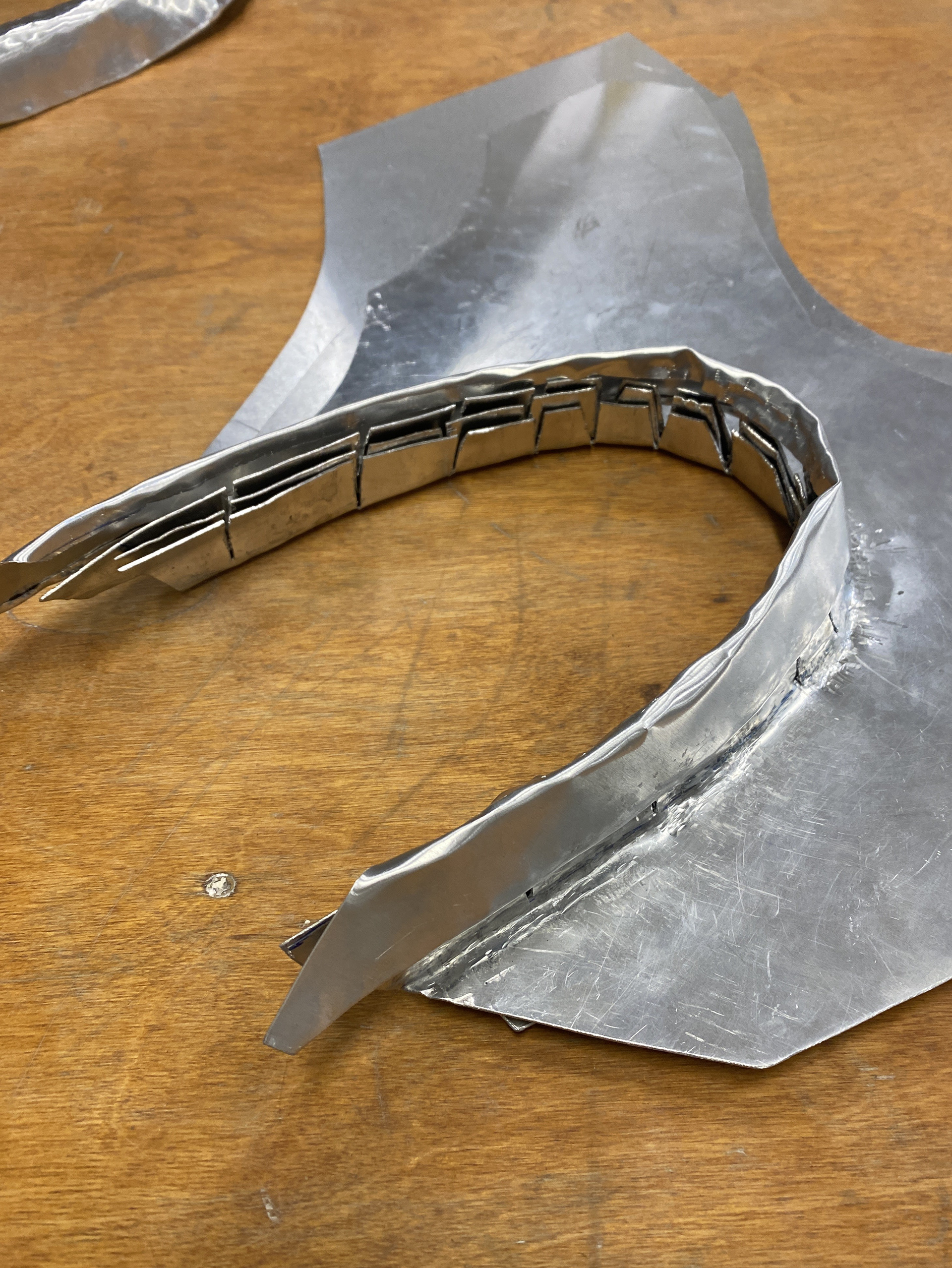
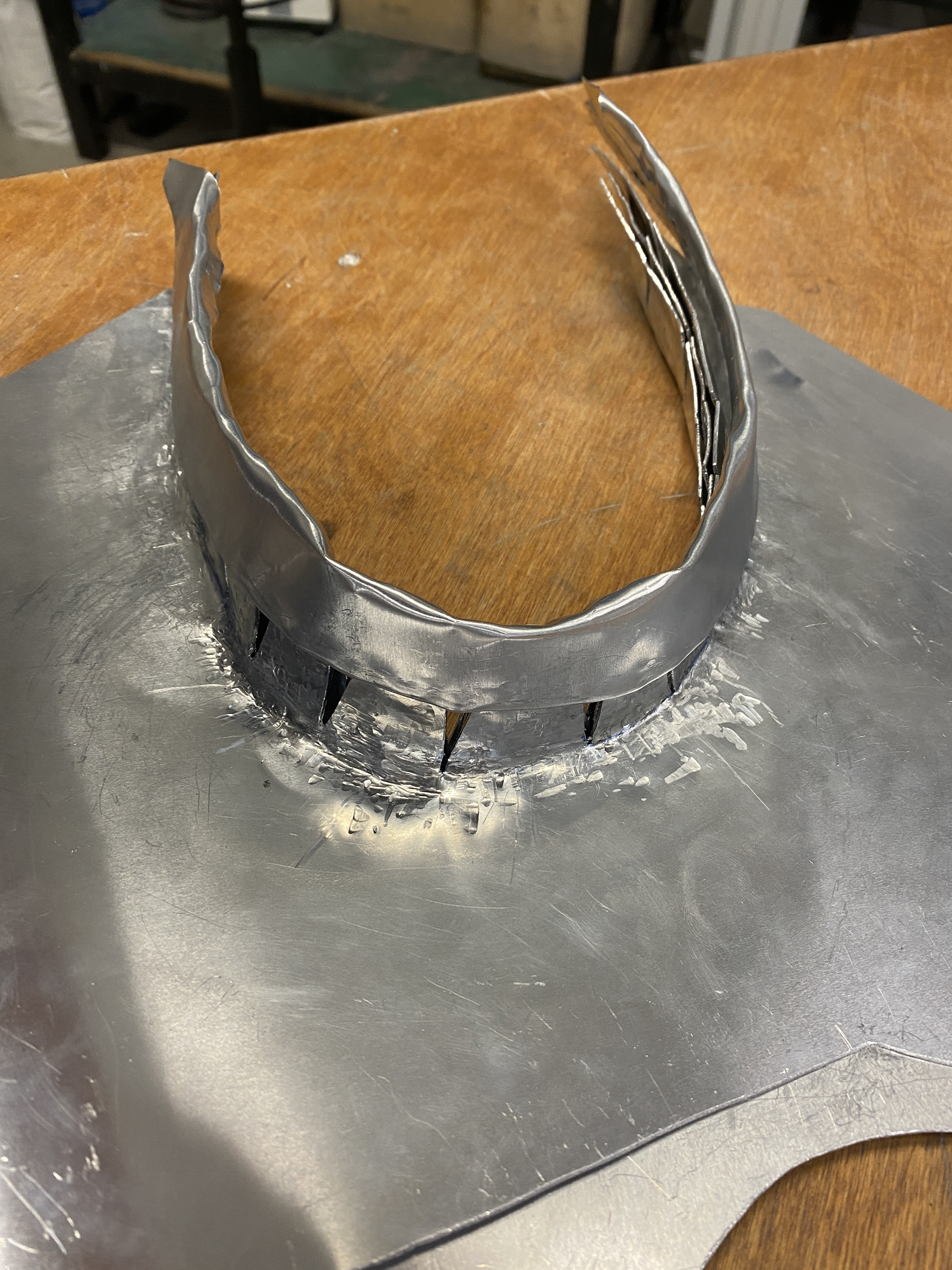
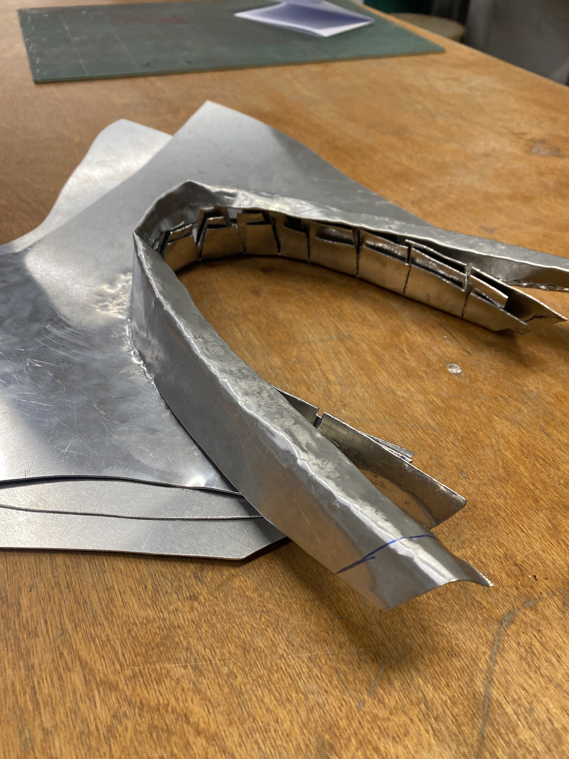
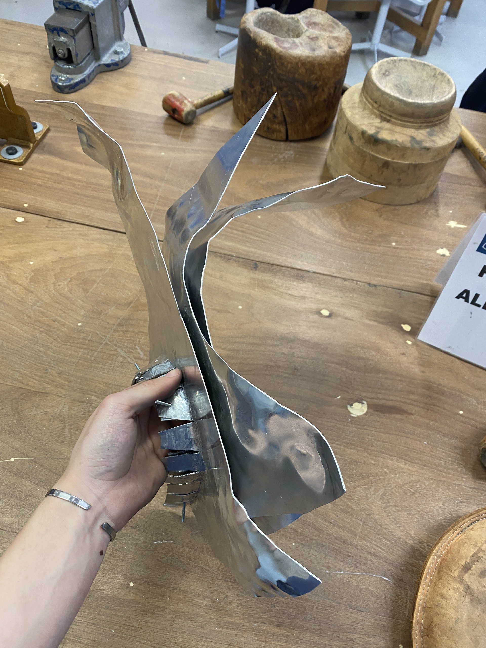
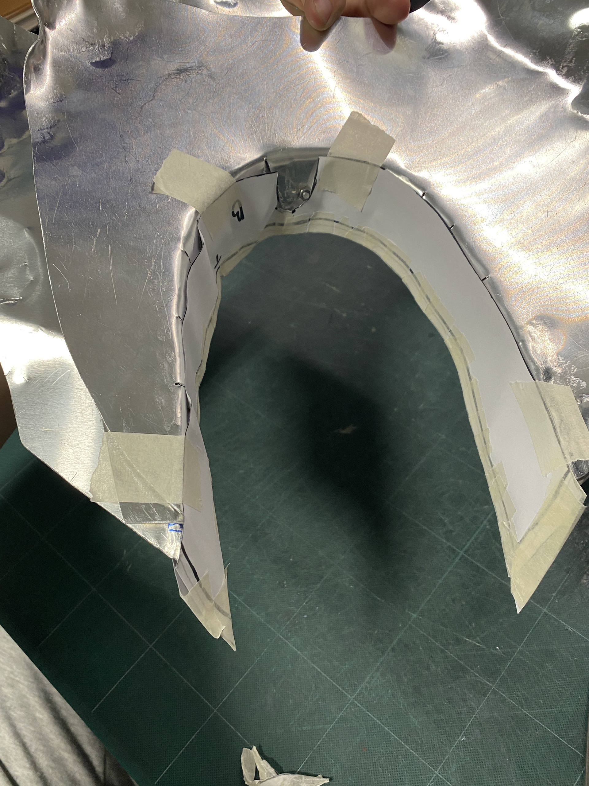
To gain a better understanding of the overall form and how I can manipulate sheet metal, I created an aluminium model. I transferred the paper template onto 1mm aluminium and cut the shapes using the bandsaw. I then rolled each sheet individually, gradually curving the flat sheet into my desired shape. I discovered the importance of keeping the design's vertical symmetry line parallel with the rollers so that all the different elements would line up correctly.
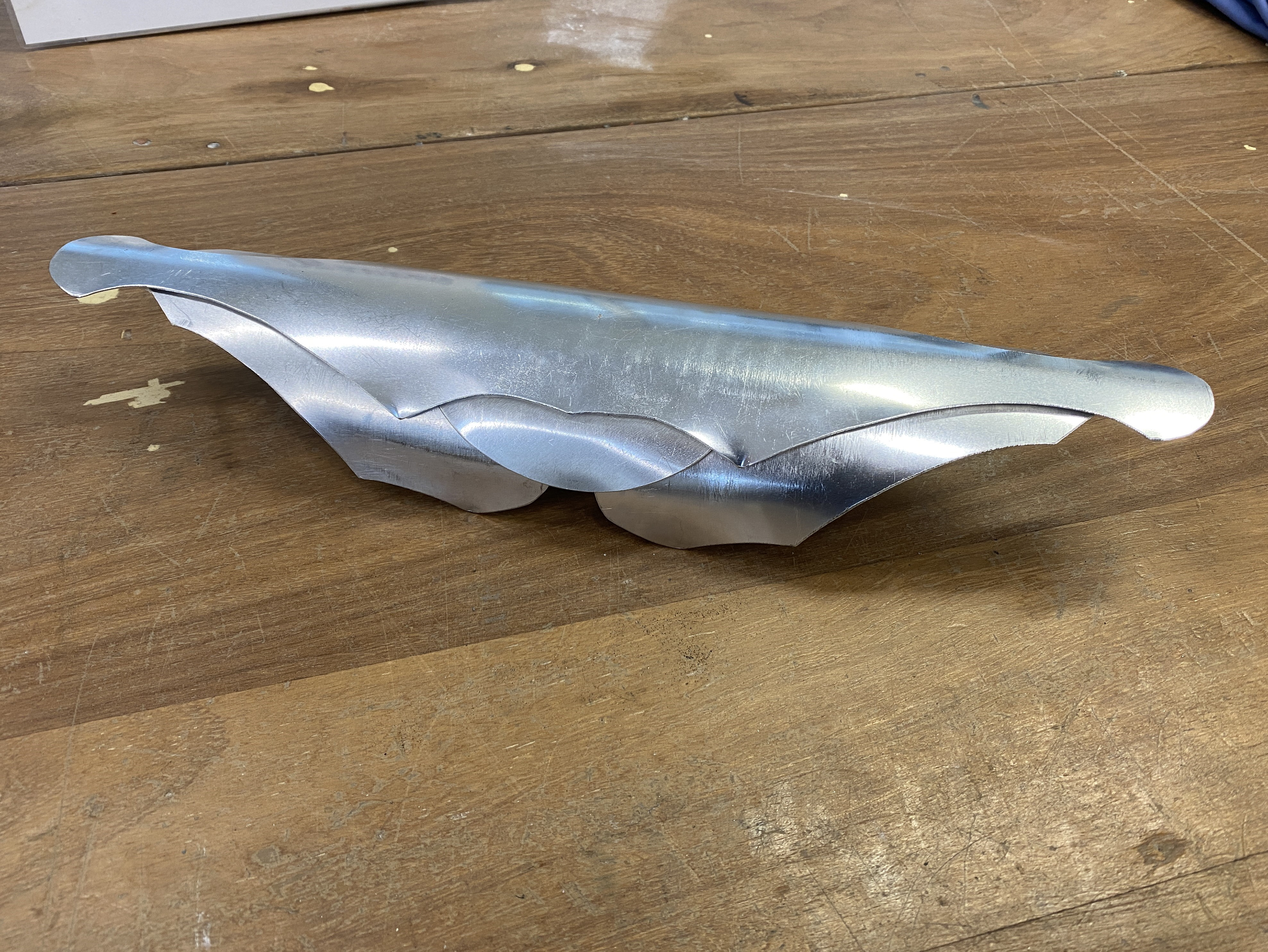
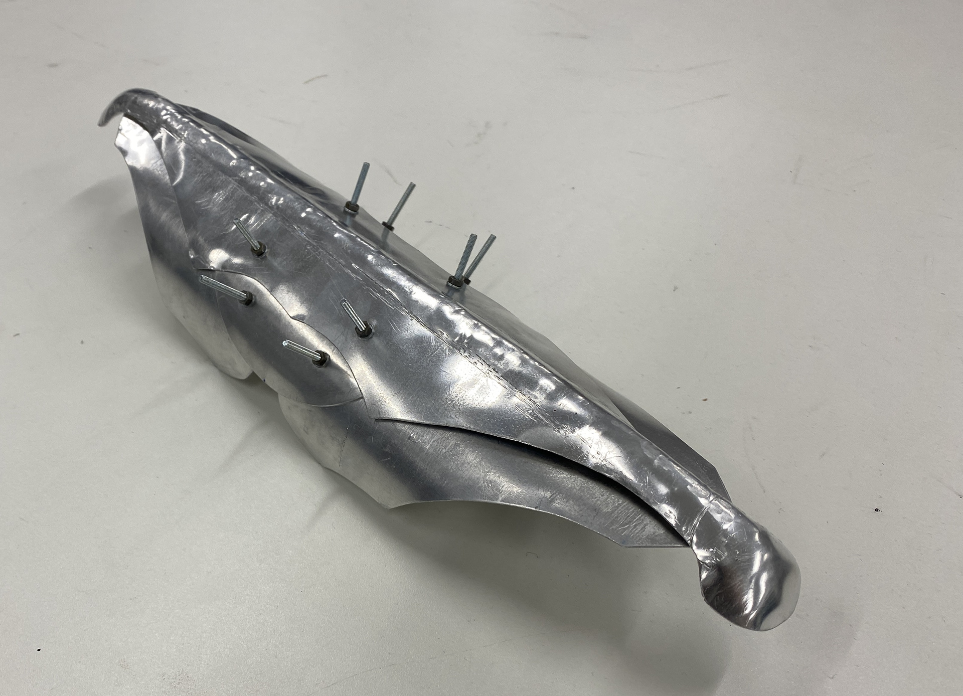
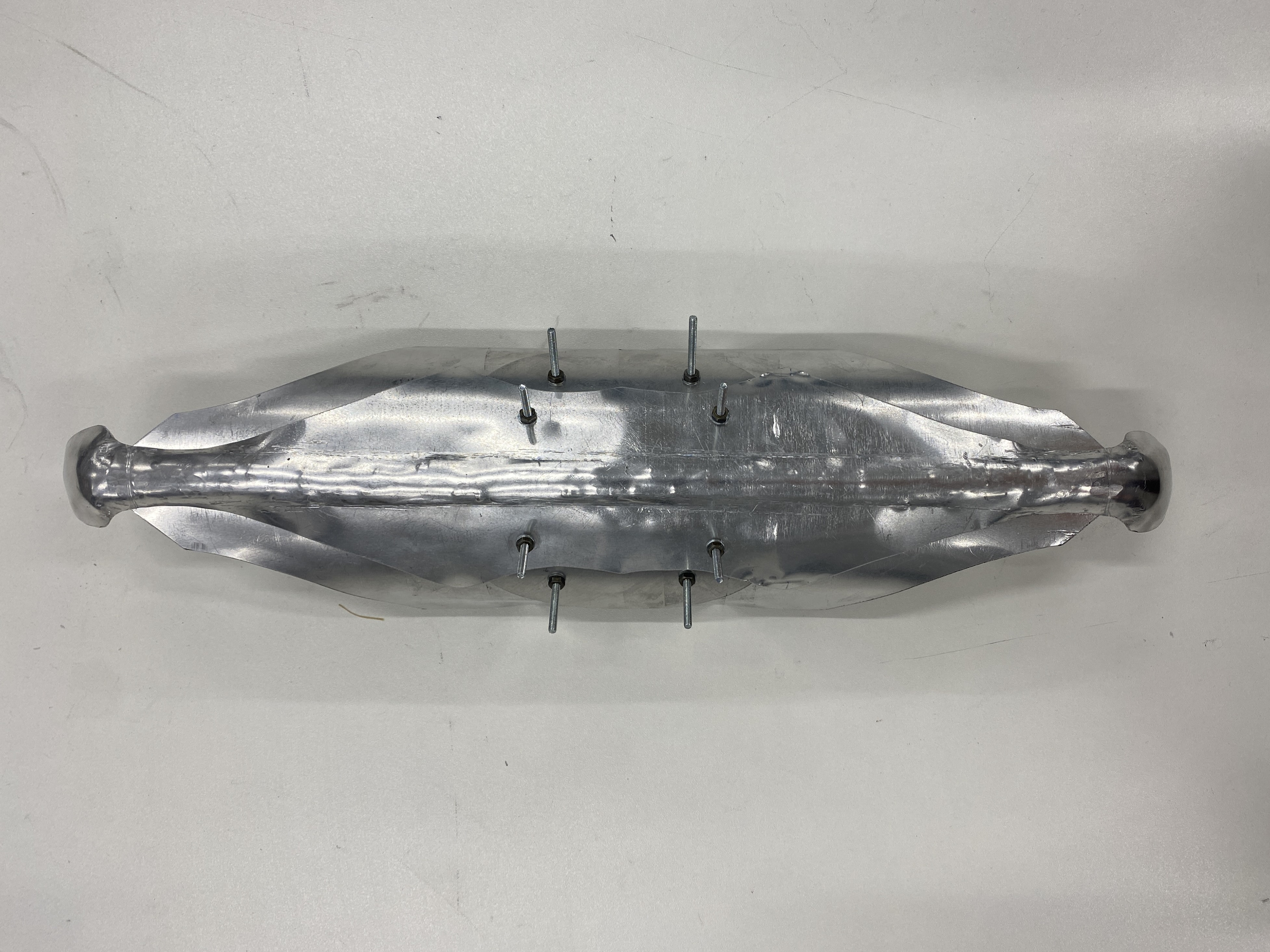
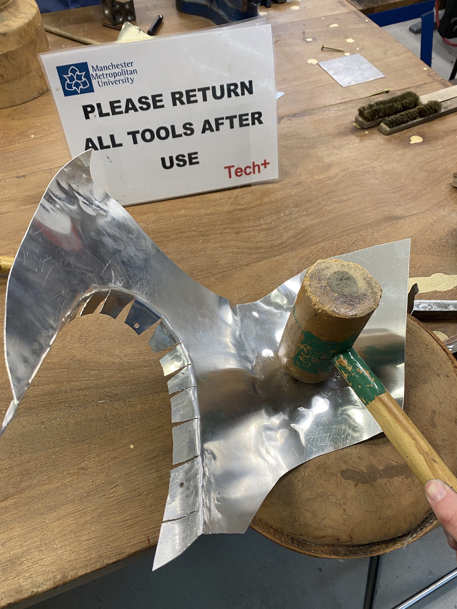
Once I had rolled the forms, I realised that my initial flat design looked too angular and precise and didn’t harmonise with the rest of the design. Therefore, I domed and bent over the rounded ends using a doming block and added in a raised line down the centre using a swage block and raising hammer. I also drilled holes for rivets but used M3 bolts to temporarily join it together so that I can easily disassemble the piece to use as references in the final product.
Aluminium armpit section (Besagew) modelling
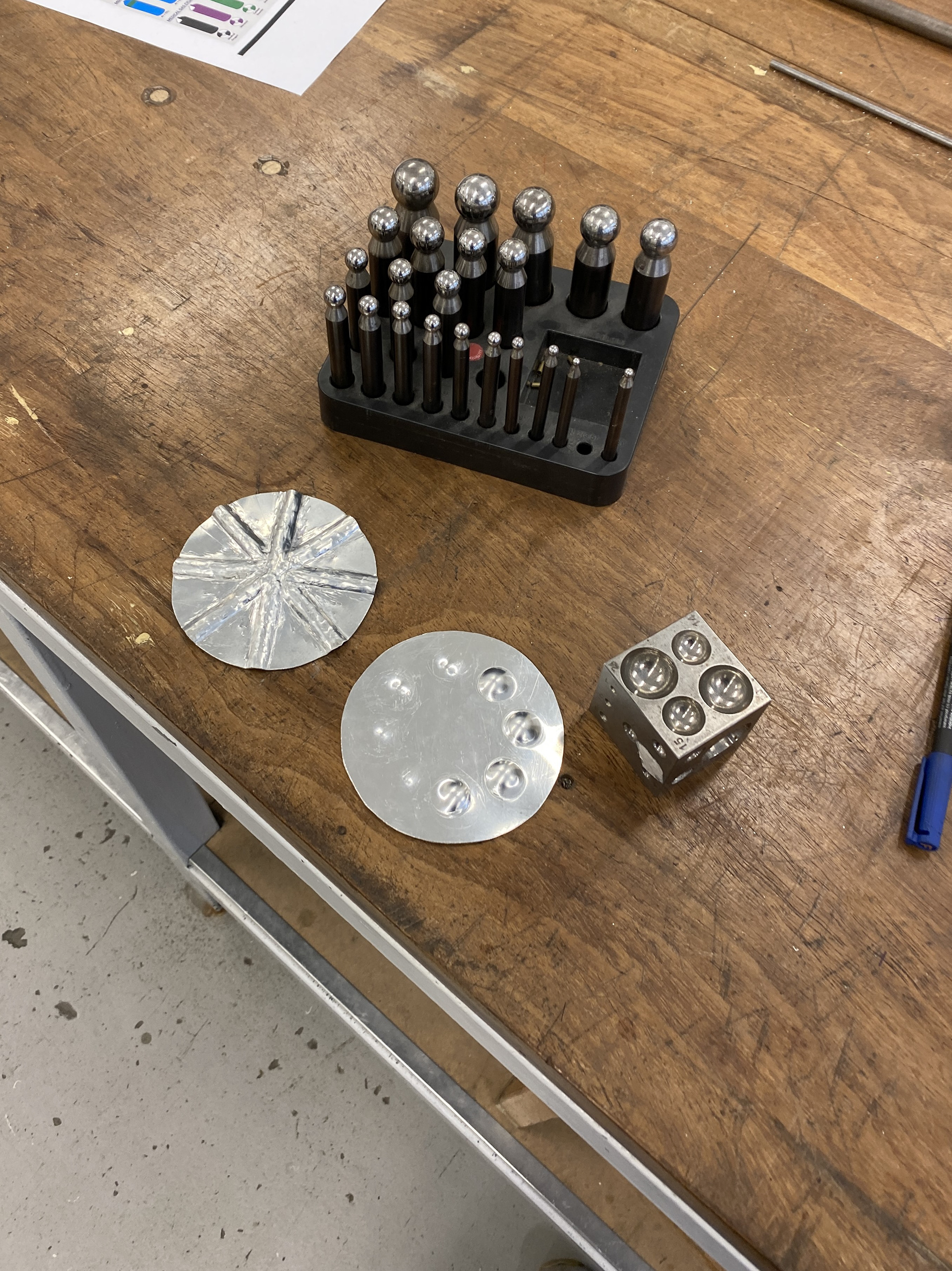
To model the Besagew, I used a series of different sized swage blocks and doming blocks to form the aluminium to the desired shape. However, when creating multiple domes next to each other, the first would become distorted and the uniformity of the design was lost. To progress this further I have chosen to only use the swage blocks to create raised linear areas in my designs.
Aluminium lower shoulder modelling
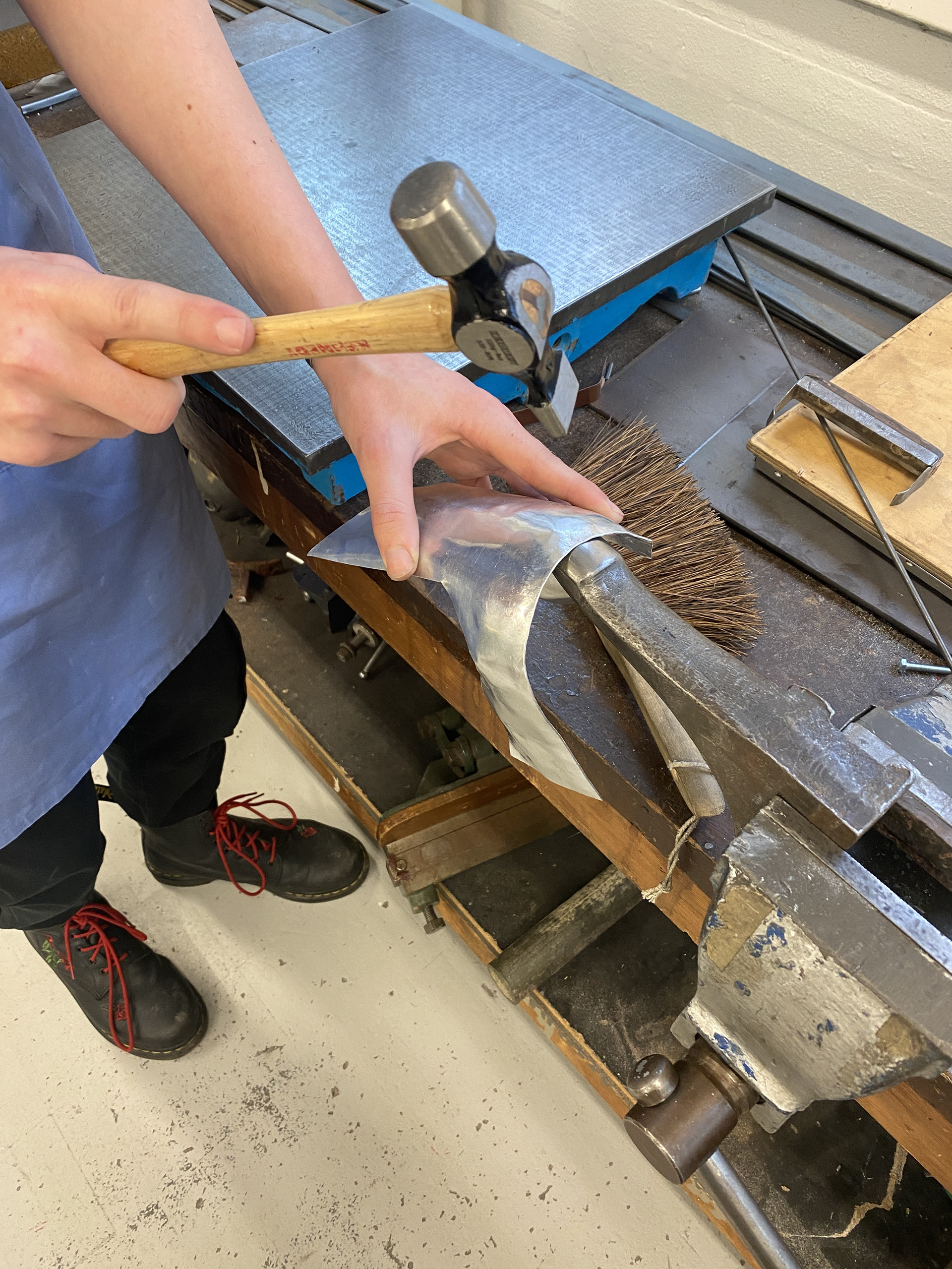
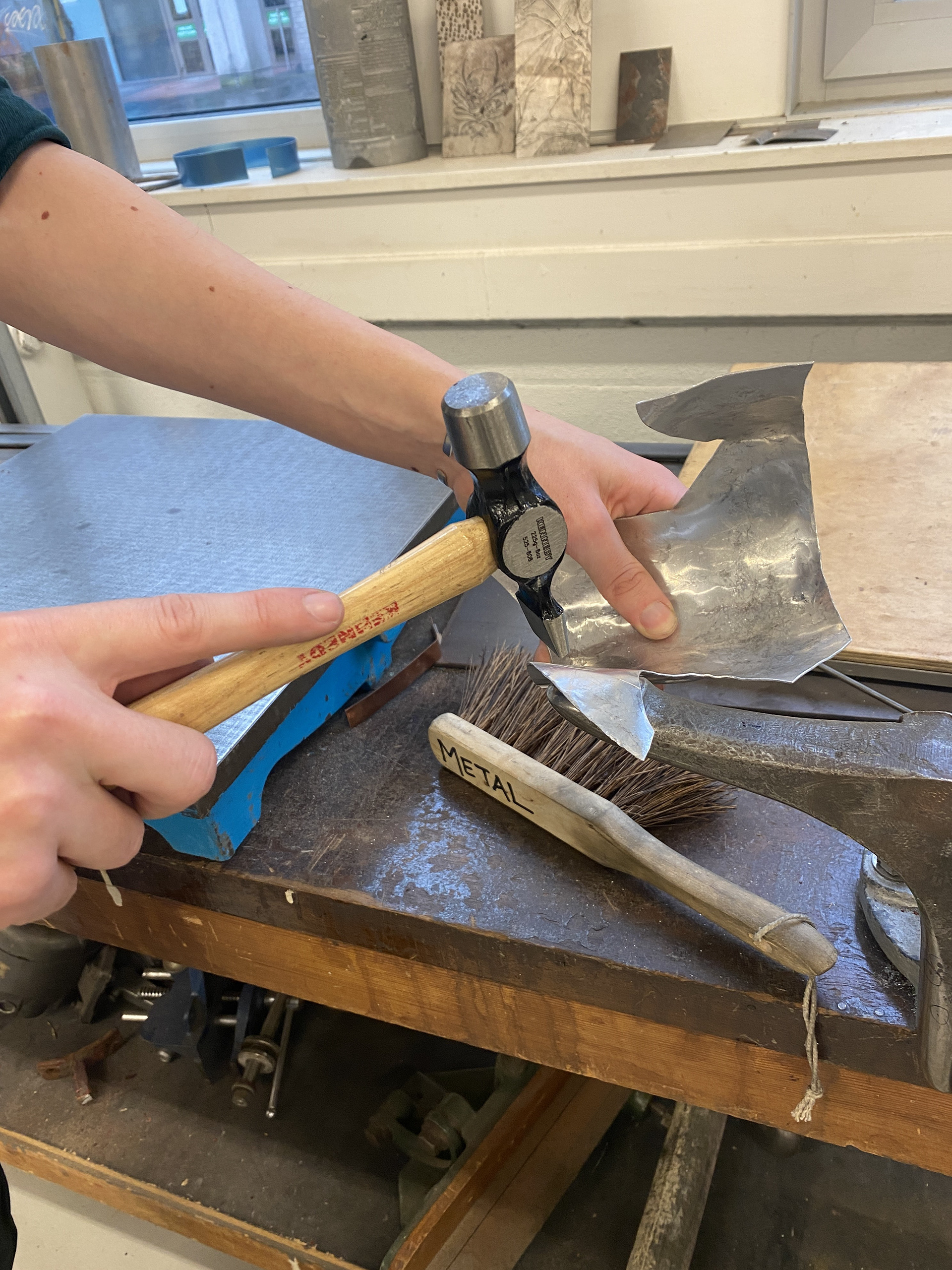
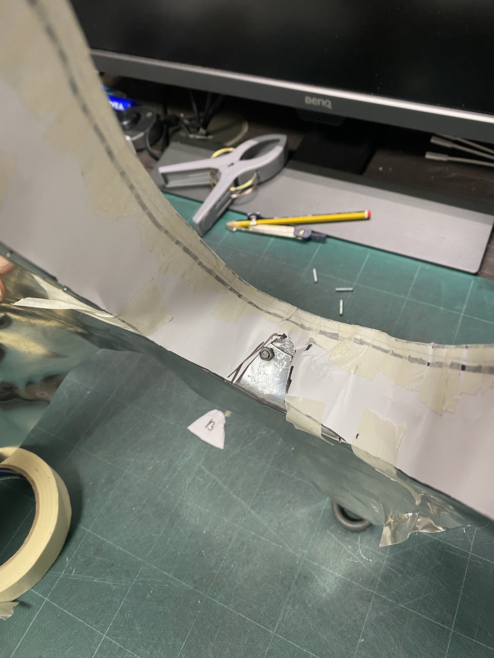
Taking this section from paper to aluminium was a simple process of using different stakes and a sandbag to form the metal into the desired shape. I continuously referenced the paper template that I had attached to the cast to work out which areas of the aluminium needed adjustments.
I found that the process of shaping the aluminium and thus work hardening was beneficial this time. Once the larger changes were made, the material stiffened up and meant smaller adjustments wouldn't shift the material as far, giving me more control over the finished shape. This is something that I will utilise when reproducing the components in copper and brass, and I will be mindful of when it is appropriate to anneal them or leave them work hardened.
Aluminium upper shoulder area modelling

Before testing the whole upper shoulder section in aluminium I needed to test raising the profile that sits against the body. This will reduce the modelling costs and give me practice with the process.

I discovered that I needed to raise the material further than initially expected to account for the concaved area between the vertical sheet and the shoulder. Additionally, I found that there wasn't enough material to bend the flat sheet into the complex curved form. Therefore, I cut two slits to allow the raised section to easily bend and not distort the rest of the flat sheet. Throughout this process I was referencing the cast arm to determine where needed adjustments. This was a much more time-consuming process than I initially thought which I will need to consider when producing the final piece.
Once I had tested the raising on a square sheet, I moved into aluminium testing the final form. I found that this was much harder and couldn't achieve the same results as before. This is due to the increase size of the sheets and every time I would raise one section another would become distorted. This was most prevalent in the narrow lower sections that would pin into the arms and stop the form from slotting over the cast. Additionally, raising such a large area meant that the flat horizontal section above the shoulder became concaved making moving material down and out even harder. This wasn't helped by the aluminium work hardening and despite annealing became too thin and weak causing cracks and holes. This is one of the limitations of modelling in aluminium compared to working directly into copper where this would be less of an issue.
I concluded that this method of raising and forming the metal over the shoulder was too time consuming and required a higher understanding of the process. Therefore, I changed my approach to progress my modelling further.
I realised that by cutting into the raised section I already needed to cover and hide these areas. Therefore, I copied my paper prototyping method of cutting several tabs to be lifted into the correct shape to create the curved form. I used the bandsaw to cut up to the edge of the raised curve and the bent the tabs by raising them. I then used a rubber mallet to curve the tabs over a stake so that the form would sit neatly over the shoulder. This method achieved the desired from and was easily repeatable for each layer of the design.
To cover the slits, I experimented with bending a thin aluminium strip which would only cover the top as the only visible section whilst being worn. However, I had the same issue with forming multiple complex curves in differing directions as previously with the raising. Therefore, I decided that to reduce the work and time to produce the final piece it would be better to cover this section in leather by extending the shoulder strap over this area. Additionally, this will give a cleaner more refined look than trying to create multiple rolled metal edges.
I moved onto the final shaping of the large sheet using a series of wooden mallets, sandbags, and dishing stumps. My aim was to curve the front section around the face and obstruct it whilst still making it safe to wear, and flare out the back section to create movement. One key component was adjusting these layers so that they would still stack and slot over each other. I did this by working from the middle layer outwards and constantly laying them on top of each other to check the fit. I bolted them together through the tab sections on the shoulder.
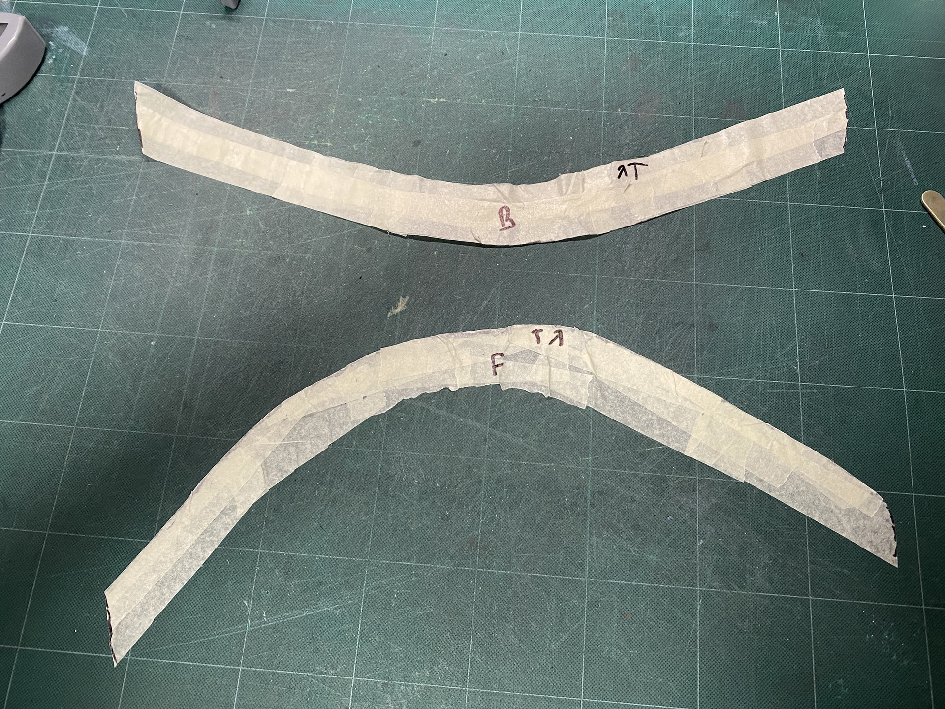
To cover the slit section of the upper shoulder I created a rough paper pattern. I used masking tape to get an exact copy and transfer the 3D form in 2D. I then added on extra seam allowance of 5mm to the joining section. When attaching this back together I found that the paper as buckling too much on the back side therefore, I added a cut out section at the top to smoothen it out.
Refining the paper pattern, I added extra material to the ends of so that I can join it all together and make a pocket design that will slip over the raised section. I experimented with adding more material to the top so that I could roll over the leather and create a feature out of the two materials joining. However, I ran into the same issue of having too many complex curves which would result in needing to use lots of sections of leather stitched together reducing the clean refined aesthetic.
Once I had the final paper pattern, I then transferred this to leather and cut it out before gluing and saddle stitching it together. I bolted the leather onto the aluminium model to emulate the rivets I will use to join the final piece together. I will also glue the leather to the copper and brass in the final piece to create a smoother finish but kept the components separate so that I could use them as a reference when making the final piece.
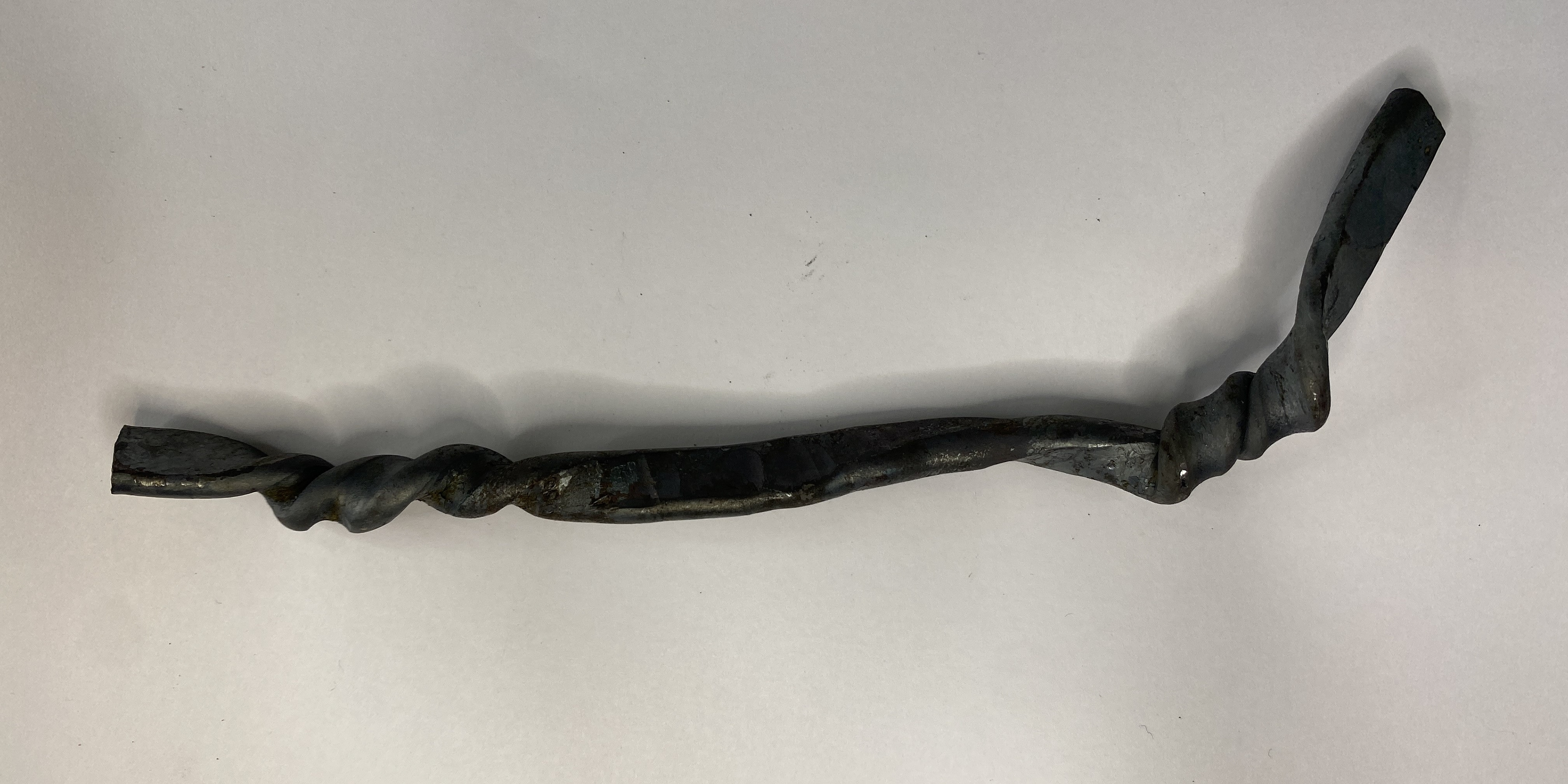
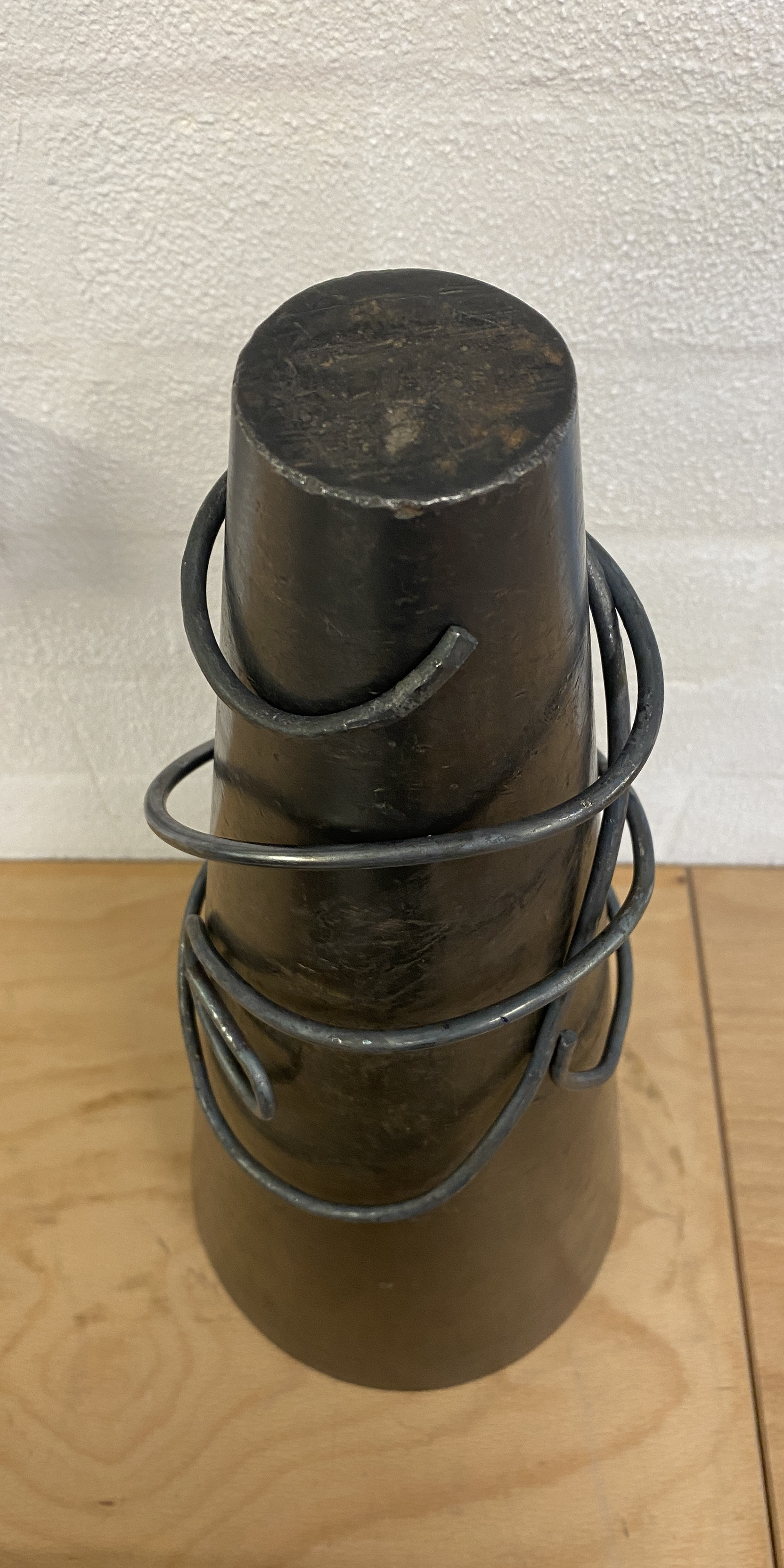
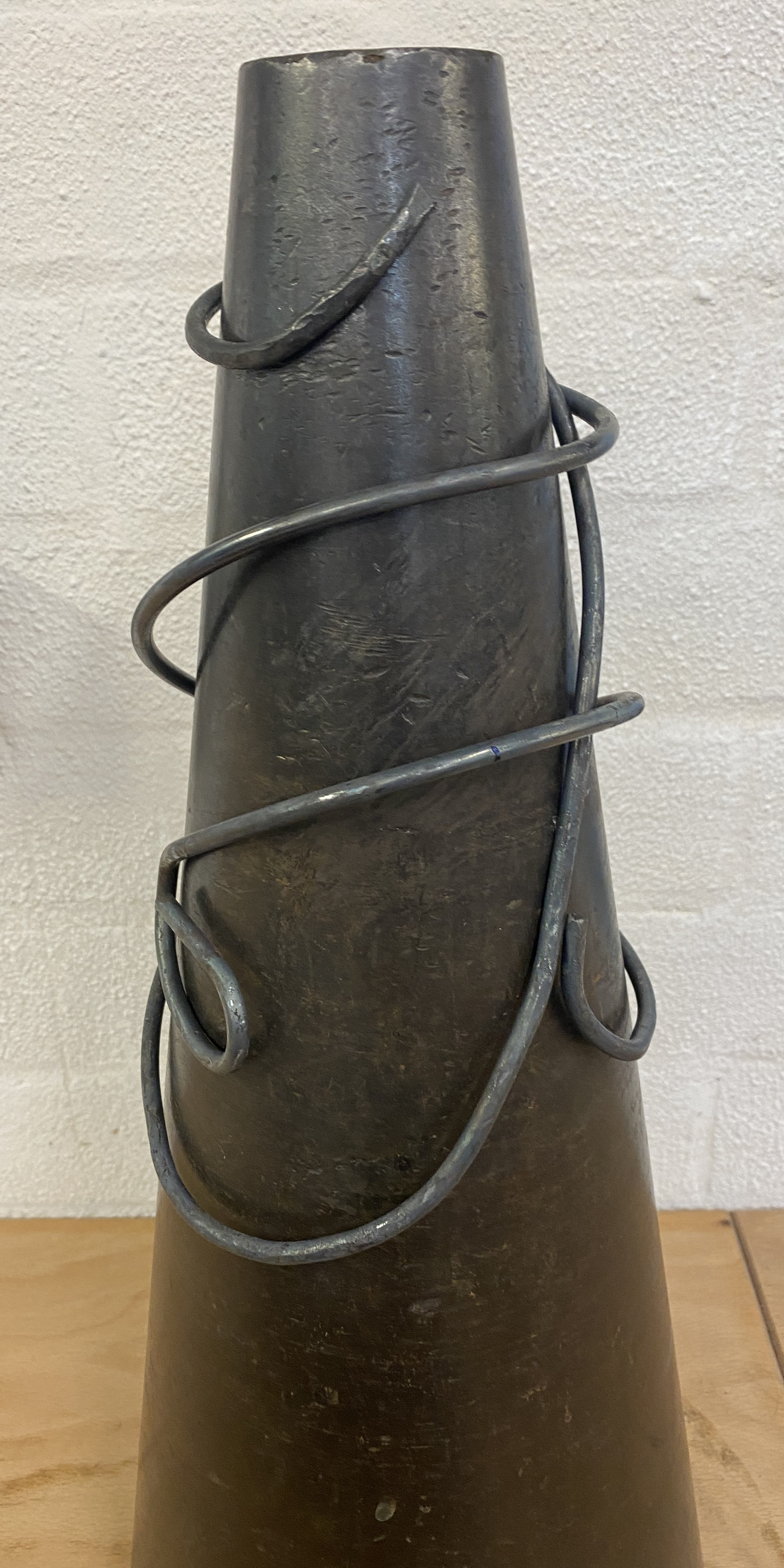
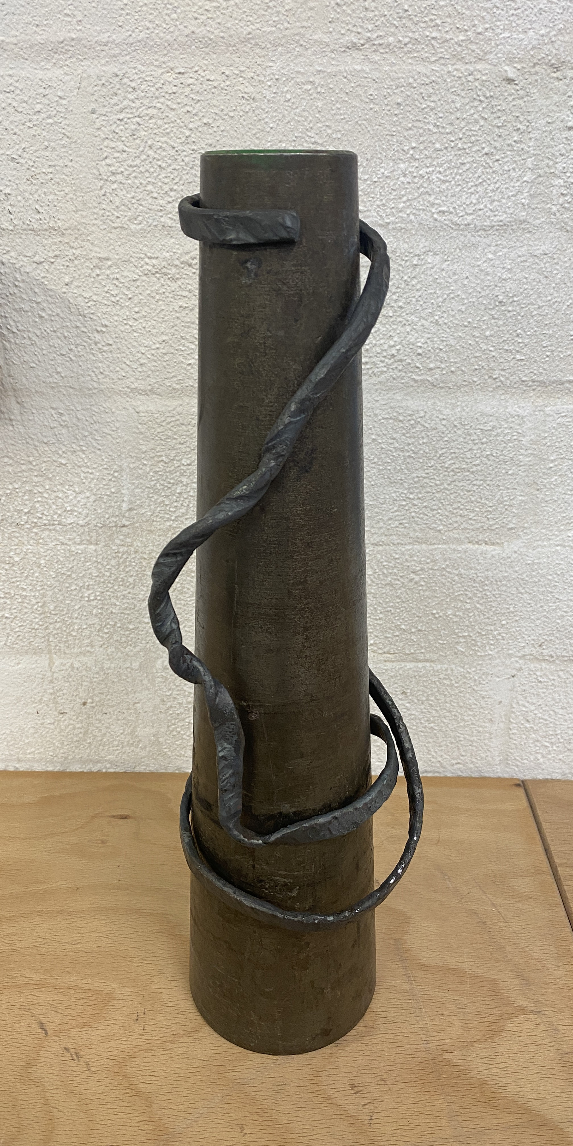
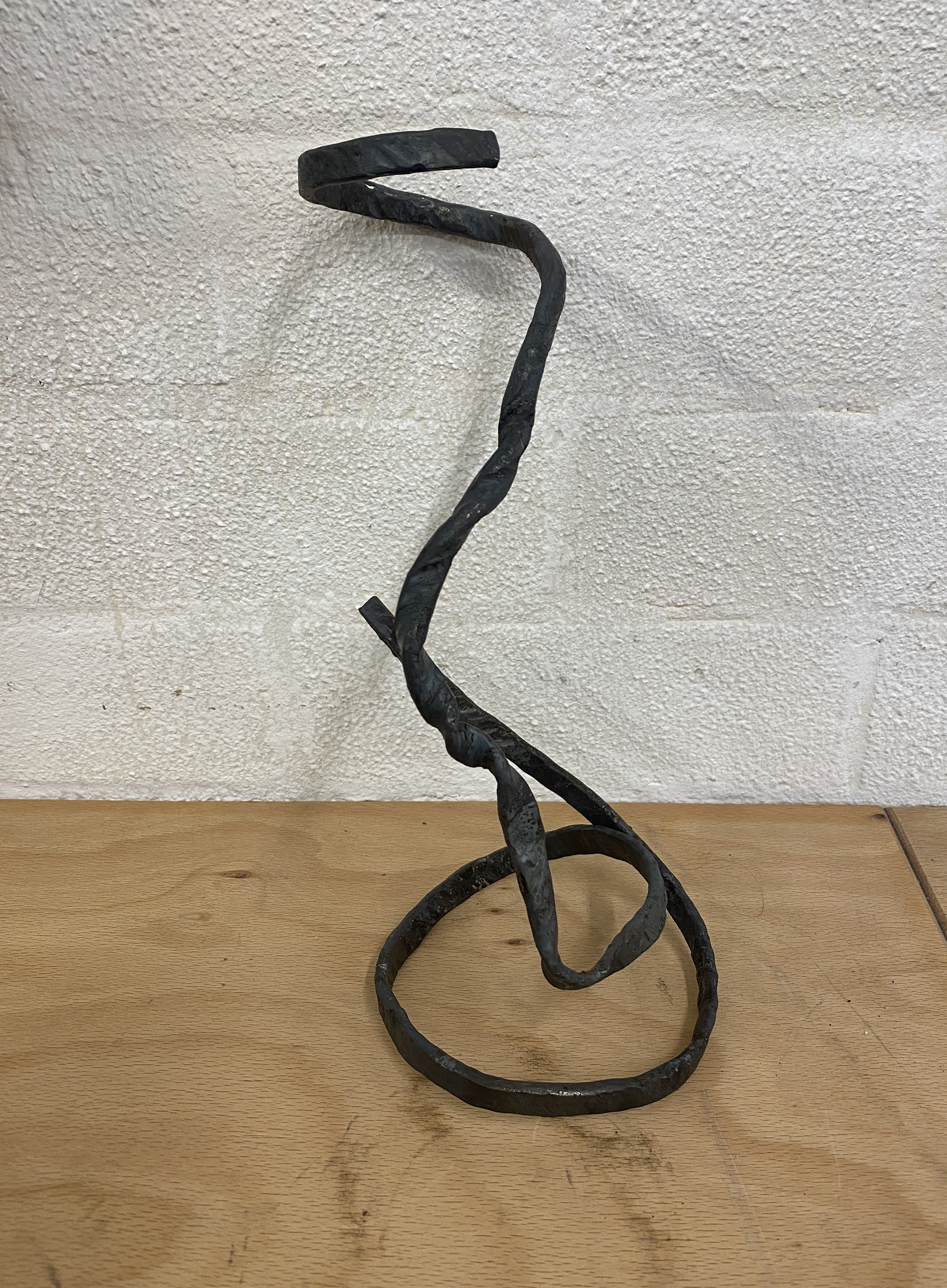
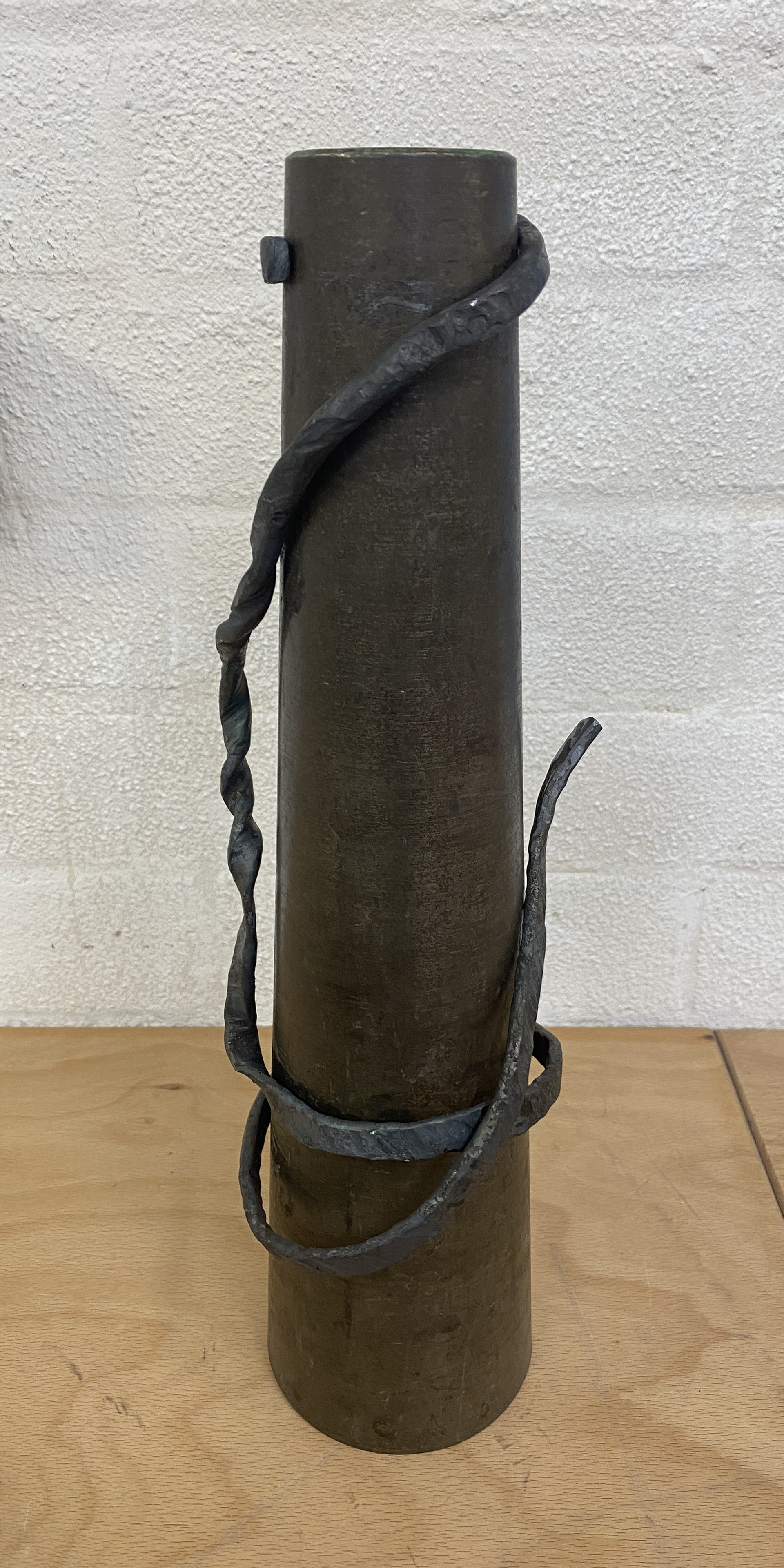
Producing the final twisted rod section

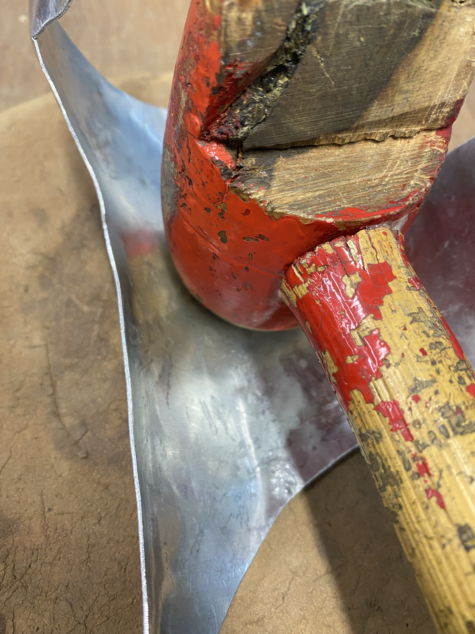
To produce my final copper twisted section, I took my aluminium model and bent the copper adjacent to it getting as close a copy as possible. I then annealed the whole piece and added texture by using a riveting hammer working around the horn of the anvil. I tried to emulate the textures and marks I had achieved in my forging samples to break up the perfectly cylindrical rod and harmonise this linear element with the forms of the sheet worked copper and brass.
I then soldered the piece in two places to increase the rigidity and structure of the overall form. Before soldering, I hammered the location so that there was a higher surface area for a stronger bond. I then bent the piece for its final adjustments ensuring it sat around the hand comfortably and could be removable from the cast arm without mis-shaping.
Producing the final piece
Making the final piece I followed all the same steps to make the aluminium mock-up but textured the copper and brass using a ball peen and riveting hammer before forming it.


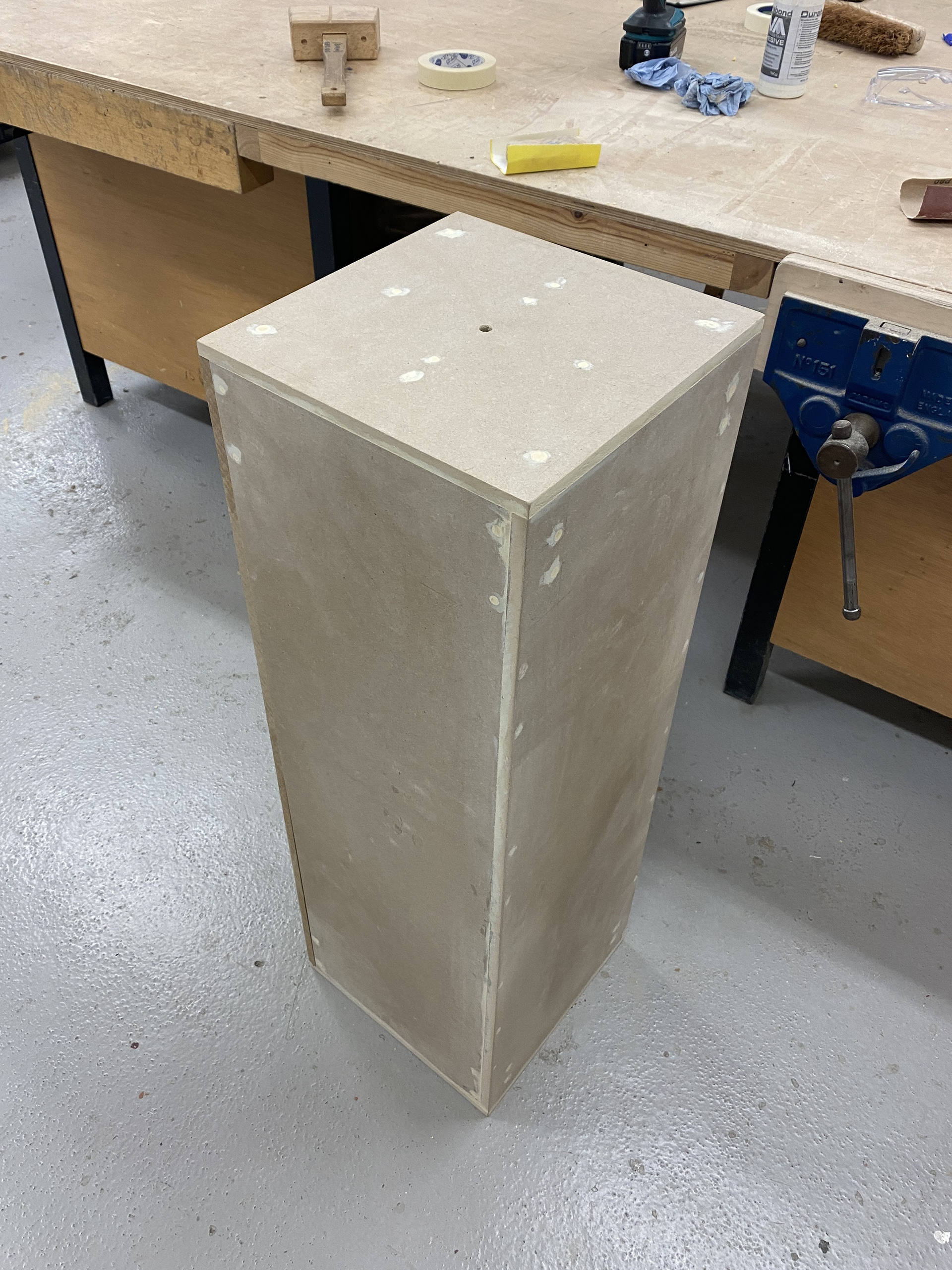
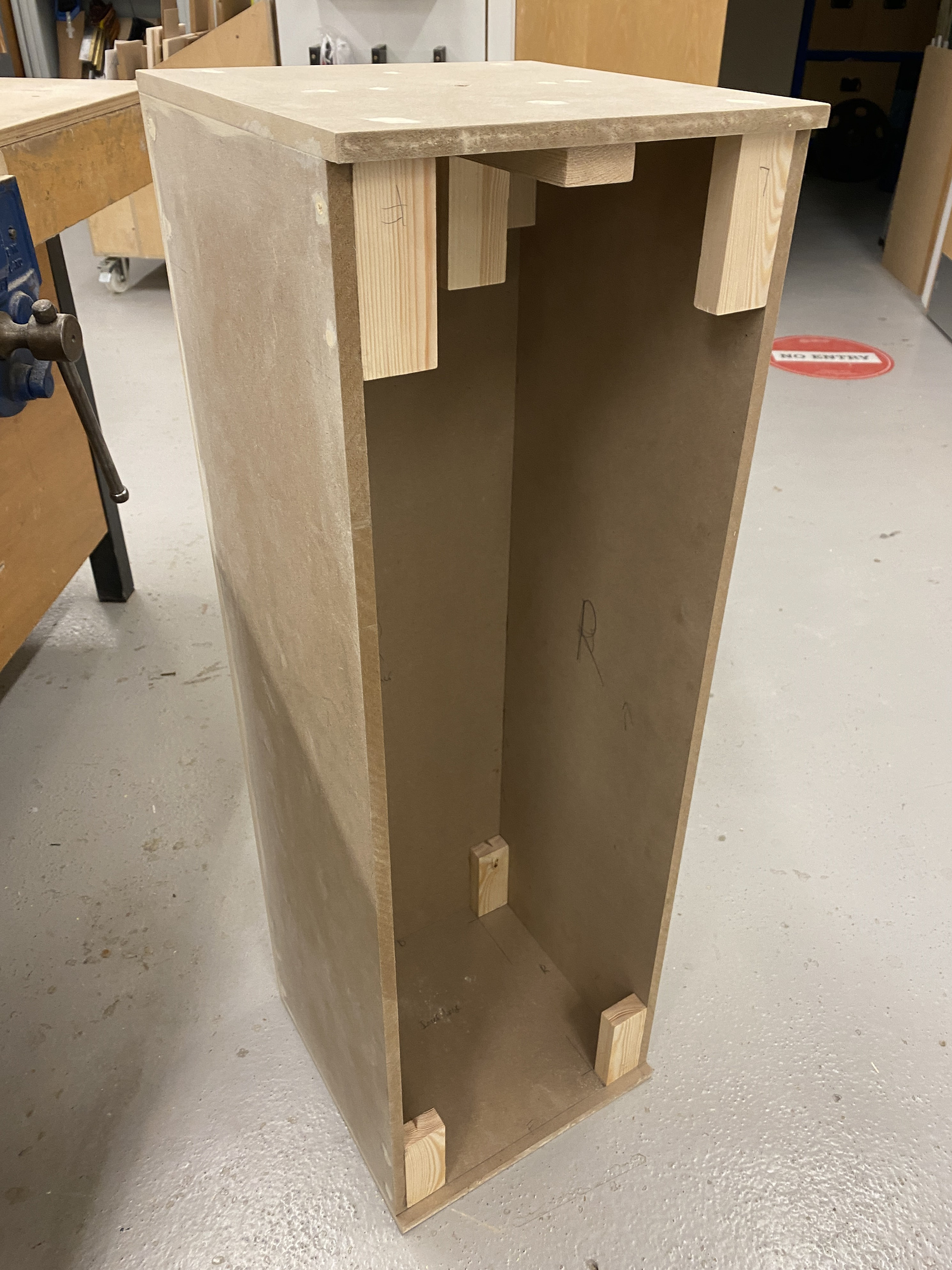
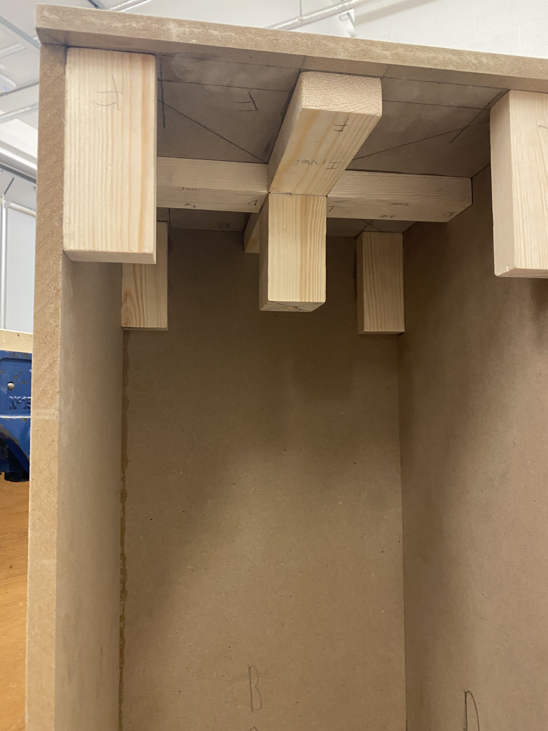
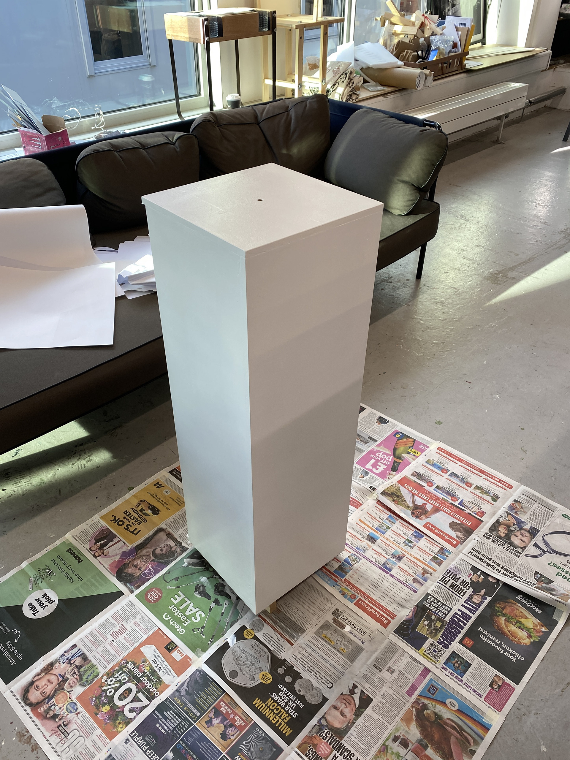
Producing the plinth and final construction